W10(LoRa AIOT Dev Kit)
Product display image:
If you’d like to view the 3D renderings, please click the link.
Product Introduction
This product is designed to provide the first AIOT hardware development platform for IoT engineers and smart hardware developers, facilitating their needs for debugging software functions, expanding peripheral modules, and testing software performance.
The product utilizes the currently mainstream ESP32-S3 processor, paired with a LoRa module and a GPS module. It integrates the commonly used WiFi, Bluetooth, and LoRa communication standards in IoT, supports the 850-930MHz frequency band and LoRaWAN protocol, adapts to Mesh networks, and meets the needs of smart cities, industrial control, and other scenarios.
Product Features
-
Equipped with an Xtensa® 32-bit LX7 dual-core processor with a clock speed of up to 240MHz, featuring built-in WiFi and BLE capabilities.
-
Integrated with LoRa and GPS modules, enabling easy communication and data transmission in wireless environments, as well as outdoor positioning and tracking.
-
On-board IMU and temperature/humidity sensors for motion detection and environmental monitoring, with wireless synchronization and upload capabilities.
-
On-board RTC clock chip for clock, alarm clock, and perpetual calendar functions, also serving as a timestamp standard for wireless communication.
-
Equipped with an audio Codec chip, compatible with mainstream LCD and OLED displays, enabling easy AI voice intercom and chat functions.
-
Equipped with a camera interface, supporting OV2640 and OV5640 cameras, for image and video capture, display, and upload.
-
Equipped with a lithium battery interface, allowing the product to operate normally without USB connection.
-
Extended IO compatible with Arduino interface, enabling compatibility with various Arduino peripheral modules and accessories
Technical Specifications
Hardware specifications
| Functional Category | Function Description |
|---|---|
| Product Name | LoRa AIOT Dev Kit |
| Model | DEVK1.0 |
| Power Supply Interface | USB TYPE-C 5V/3A |
| Main Control Chip | ESP32-S3R8 Xtensa® 32-bit LX7 dual-core microprocessor, with a clock speed up to 240MHz |
| LoRa Module | EBYTE E22-900MM22S supports the 850-930MHz frequency band and LoRaWAN protocol |
| GPS Module | Quectel L76K supports multiple satellite systems including GPS, GLONASS, BDS, and QZSS |
| LCD | Supports a 3.5-inch capacitive touch display screen, FPC (SPI+I2C) interface, resolution of 320x480, and 262K colors |
| Supports 3.5-inch TFT Arduino (LCD) interface display with a resolution of 320*480 | |
| Supports a 1.54-inch ISP full-view SPI interface display with a resolution of 240x240 and full-color RGB | |
| Supports a 1.3-inch OLED SPI interface LCD display with a resolution of 128x64 and full-color RGB | |
| Supports a 1.47-inch TFT SPI interface LCD display with a resolution of 172x320 and full-color RGB | |
| Camera | Supports OV2640 2 million pixel camera |
| Support OV5640 5 million pixel camera | |
| Audio codec | ES8311 is a low-power audio codec chip with 24-bit resolution, supporting sampling frequencies ranging from 8 to 96kHz |
| Temperature and Humidity Sensor | SHT41 Temperature: 0 - 75℃, accuracy ±0.2℃; Humidity: 0 - 100%, accuracy ±2% |
| IMU Sensor | QMI8658 6-axis MEMS IMU chip, integrating 3-axis gyroscope and 3-axis accelerometer |
| RTC real-time clock | The PCF85063 RTC calendar chip boasts extremely low power� consumption, with a standby current of just 0.25μA |
| Power Management | AXP2101 is a highly integrated PMIC, featuring built-in 4-channel DC-DC converters and 1-channel fuel gauge |
| IO expansion port | Compatible with Arduino interface, featuring 2 sets of UART, 1 set of ADC, 1 set of SPI, and 1 set of I2C interfaces |
| Debugging interface | 1 set of JTAG interface |
| USB communication port | One set of USB 2.0 communication interfaces, primarily utilizing the USB CDC function |
| Button | 1 reset button, 1 BOOT button |
| Storage | External 16MB SPI Flash |
| Number of layers | 4 floors |
| Board material | RF-4 (glass fiber board) |
| Veneer weight | 30.8g |
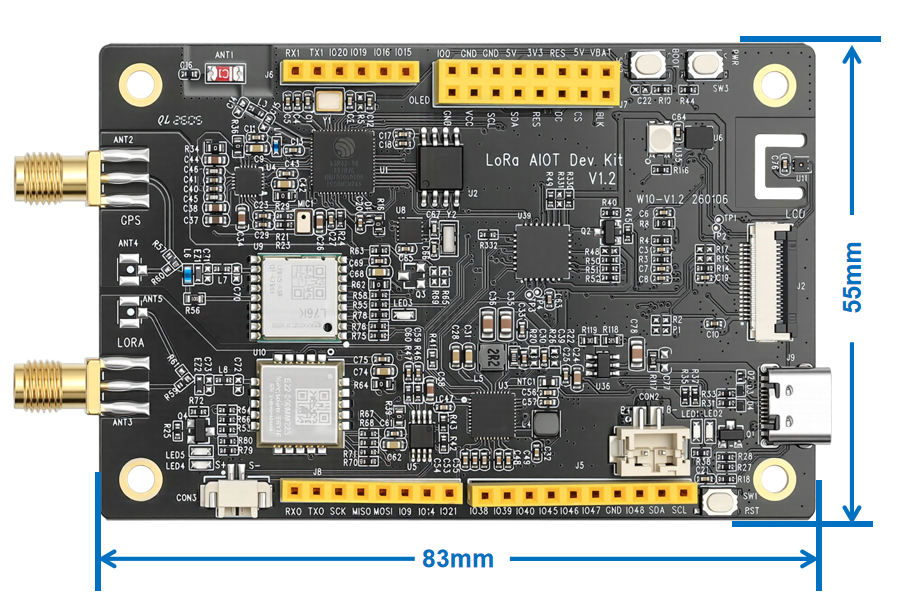
| Fixed hole spacing | 73.80*45.00mm |
| Board size | 83.40*55.00mm |
| Operating Temperature | -40℃~85℃ |
| Product Certification | FCC、CE、RoHs |
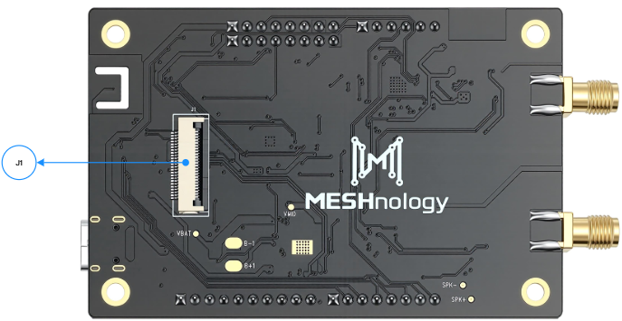
Hardware Manual
| Number | Resource description |
|---|---|
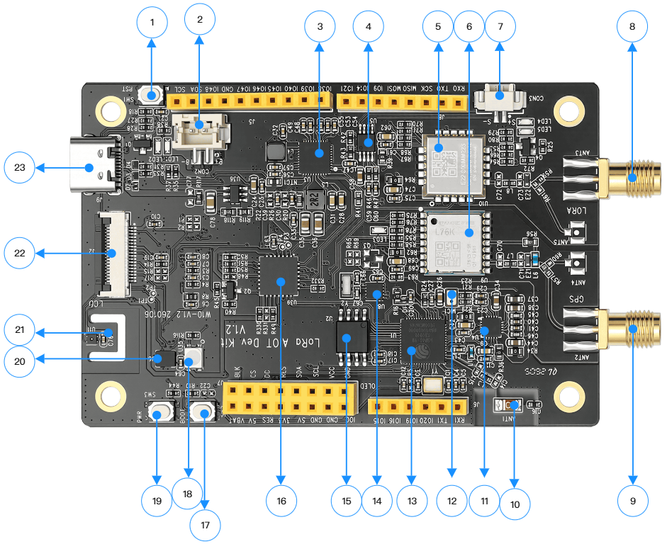
| 1 | RESET button, press to restart the device, used for fault recovery and program re-execution |
| 2 | PH2.0 lithium battery interface, connected to a 3.7V lithium battery via a PH2.0_2PIN connector |
| 3 | The AXP2101 power management chip is responsible for power distribution, voltage regulation, and power consumption control, ensuring stable power supply to the device |
| 4 | The audio power amplifier NS4150B can deliver an output power of up to 2.8W under a 4Ω load condition, with a maximum output of 3W |
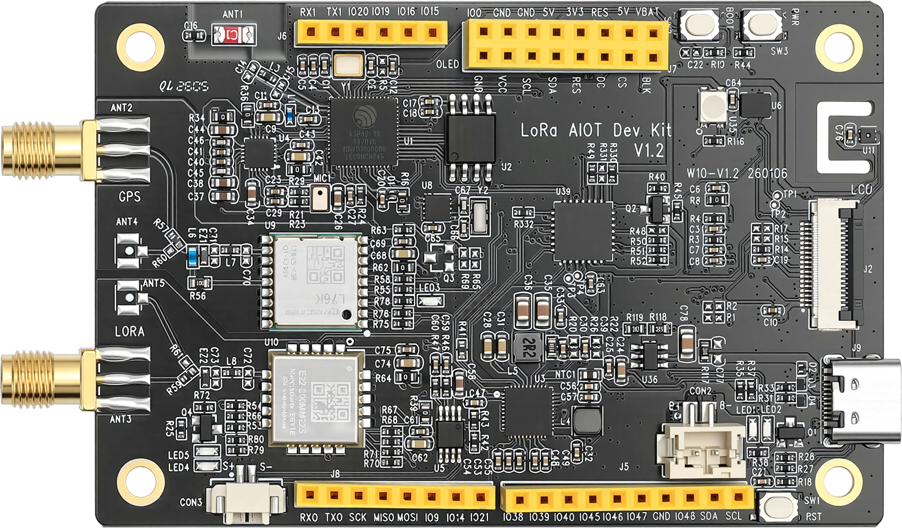
| 5 | E22 - 900MM22S LoRa module, based on the SX1262 chip, operates in the 850 - 930MHz frequency band, with a maximum transmission power of 22dBm |
| 6 | Quectel L76K GPS module supports multiple satellite systems including GPS, GLONASS, BDS, and QZSS |
| 7 | PH1.25 speaker connector (loudspeaker) interface, used for audio output, supports speakers up to 3W |
| 8 | SMA socket, connected to LoRa 850~930Mhz antenna |
| 9 | SMA socket, connected to LoRa 850~930Mhz antenna |
| 10 | The patch ceramic antenna enables wireless signal (Wi-Fi, Bluetooth) transmission and reception, and can operate without the need for additional external antennas |
| 11 | ES8311 is a low-power audio codec chip that processes audio signals (encoding and decoding), enabling devices to record and play sound |
| 12 | Microphone, used for collecting sound signals, enabling recording and voice interaction functions |
| 13 | ESP32 - S3R8 core controller is a system-on-chip (SoC) integrating Wi-Fi and Bluetooth functions, operating at a frequency of 240MHz, and also incorporates 8MB of pseudo-static random access memory (PSRAM) for extended storage |
| 14 | The PCF85063 RTC clock chip precisely provides a time reference, enabling devices to have real-time clock functionality |
| 15 | W25Q128JVSIQ 16MB capacity NOR-Flash memory chip |
| 16 | The MCP23017 is a 16-bit I²C serial bus I/O expansion chip that supports a wide voltage range of 1.8 V to 5.5 V and features interrupt outputs, weak pull-up functionality and configuration registers |
| 17 | BOOT button, start mode selection button, often used in conjunction with the reset button, for programming devices |
| 18 | 3030 0.6W RGB LED light |
| 19 | PWR power button, used to control the power-on/off of the device |
| 20 | SHT41 temperature and humidity sensor, featuring an I²C interface, boasts high accuracy (±0.1°C/±1.5% RH), low power consumption, and a compact size (2.5×2.5×0.9mm) |
| 21 | QMI8658 six-axis inertial measurement unit (IMU), including 3-axis gyroscope (for measuring angular velocity) and 3-axis accelerometer (for measuring acceleration) |
| 22 | 3.5-inch LCD display FPC holder, integrating SPI, I2C, and SDIO interfaces |
| 23 | Type-C interface, used for device power supply and data transmission |
Hardware interface
| Interface Name | Image Position Marker | Functional Description |
|---|---|---|
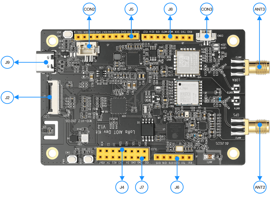
| USB Type-C interface | J9 | Power supply (5V/3A, supports PD fast charging) and data transmission, USB 2.0� CDC function |
| LoRa antenna interface | ANT3 | SMA male-female LoRa 850~930Mhz rod antenna or external antenna |
| GPS antenna interface | ANT2 | SMA external screw internal needle GPS active antenna |
| Lithium battery interface | CON2 (interface definitions from top to bottom) | PH2.0_2PIN connector, input 3.7~4.2V, pin 1 for GND, pin 2 for VBAT+ (battery positive input) |
| Horn interface | CON3 | PH1.25 interface, 1 pin SPK+ (audio output positive), 2 pins SPK- (audio output negative), supports up to 3W speaker |
| Camera interface | J1(CAM FPC) | 24Pin FPC interface, supporting OV2640/OV5640 cameras, including power, data, and control pins |
| LCD FPC interface | J2 | 18Pin FPC interface, supporting 3.5-inch capacitive touch screen, including SPI/SDIO/I2C interfaces and backlight control |
| IO expansion interface | J5/J6/J7/J8 | Compatible with Arduino standards, including UART, SPI, I2C, GPIO and other pins, supports external module expansion |
Product dimensions
Product dimensions image:
Instructions for Use
Software:Arduino、flash_download_tool
Hardware:
-
W10(LoRa AIOT Dev Kit)
-
USB cable, type A male to type C male, x1
-
Equipped with a 1.54-inch ISP full-view SPI interface display
-
Equipped with PH1.25 interface speaker
-
Equipped with GPS antenna
-
Equipped with LoRa antenna
Xiaozhi AI Application
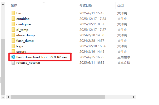
Firmware flashing
flash_download_tool
Download the flash_download_tool
https://www.espressif.com.cn/en/tools-type/flash-download-tools
Open the tool program
Select the type of ESP32-S3

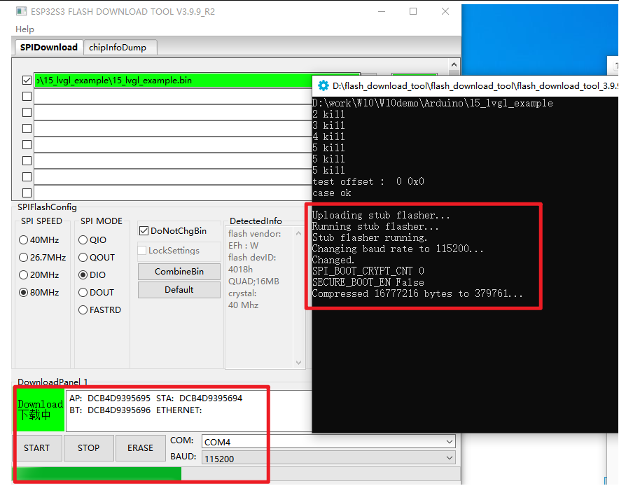
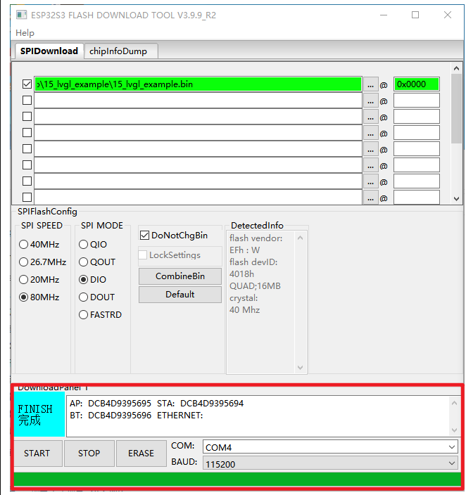
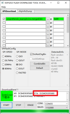
Select the bin file that needs to be burned, specify to start burning from the 0x00 address, and choose SPI SPEED and SPI MODE. Click START to proceed with the burning
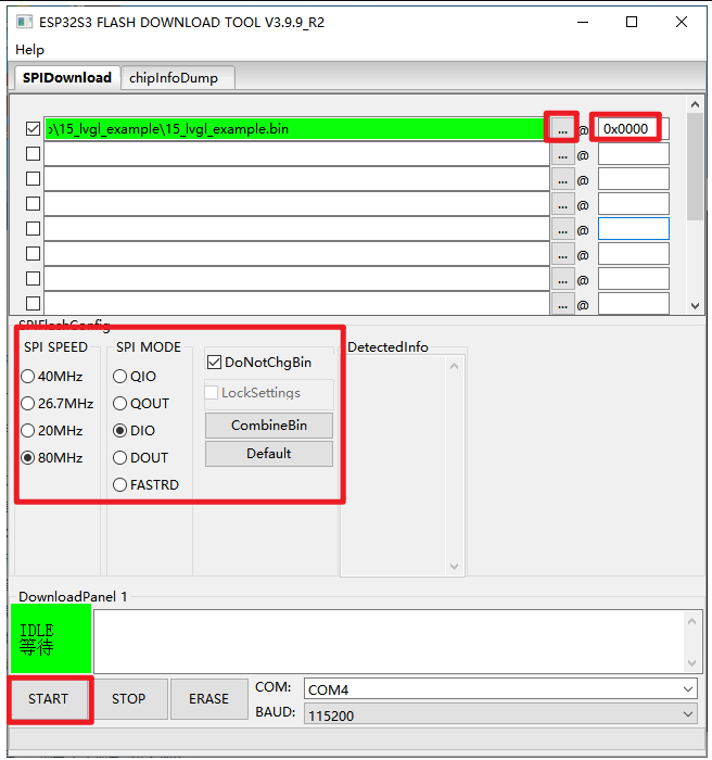
You can see the burning process on this interface
Burn completed
Basic Usage
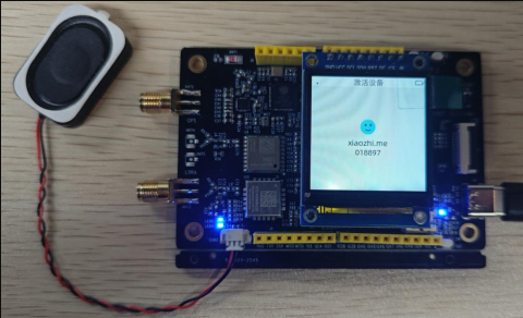
After the firmware is programmed, a prompt message will be displayed on the display screen
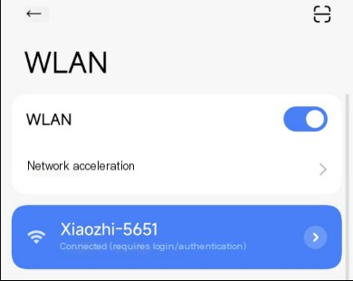
Start the network configuration
- Connect to the device's WiFi network using a mobile phone or computer: Xiaozhi-xxxxxx. After successful connection, the device's network configuration page will automatically redirect. If it does not redirect automatically, you need to manually open a browser and visit http://192.168.4.1
-
On the network configuration page, select the WiFi name (only supports 2.4G, and the maximum compatibility option must be turned on for iPhone hotspots). The SSID will be automatically filled in. Enter the password below, and then click the "Connect" button
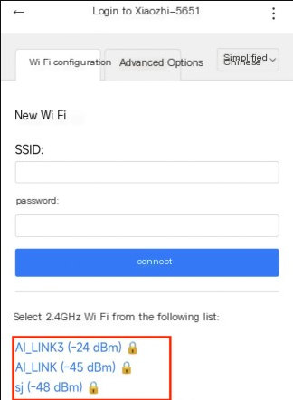
-
After successful connection, the device will automatically restart. If it does not restart automatically, you need to manually power on the device again
Add new device to the management backend
-
Ensure that the device is connected to the Internet and a prompt appears asking to add the device with a 6-digit device verification code (which can be repeated to wake up and re-listen)
-
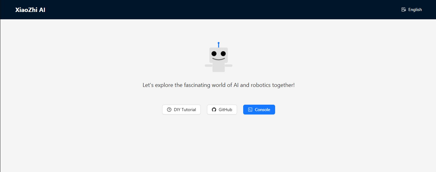
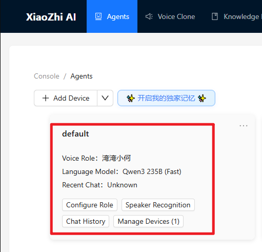
Click here to visit the Xiaozhi AI Chatbot - Control Panel backend: https://xiaozhi.me. If you haven't registered, please create an account first
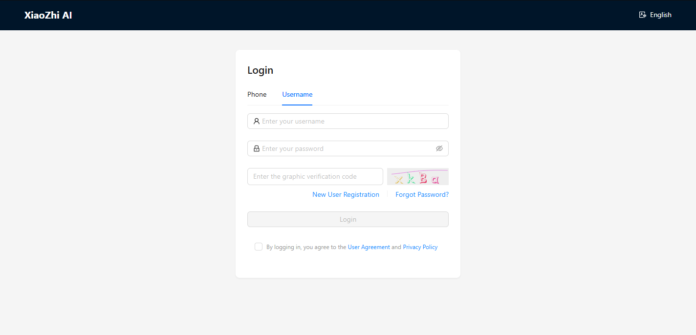
Login account
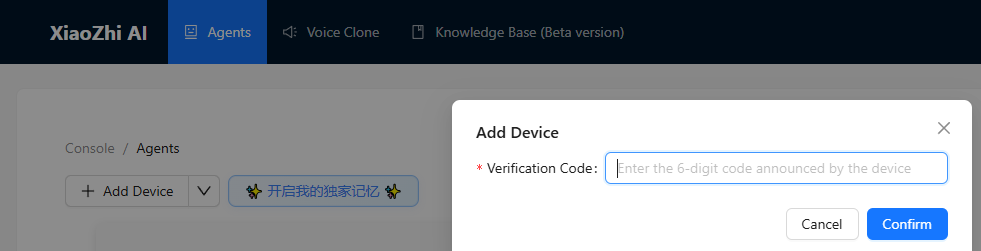
Use the verification code displayed on the screen and being played to proceed with the addition
-
The device will be automatically activated and displayed on the "Device Management" page, ready for normal use.
-
Use "Hello, XiaoZhi" to wake up the device, and then you can engage in voice conversations
Xiaozhi's additional learning links
Arduino development
Environment setup
Download and install Arduino IDE
Arduino download websit:arduino.cc/en/software
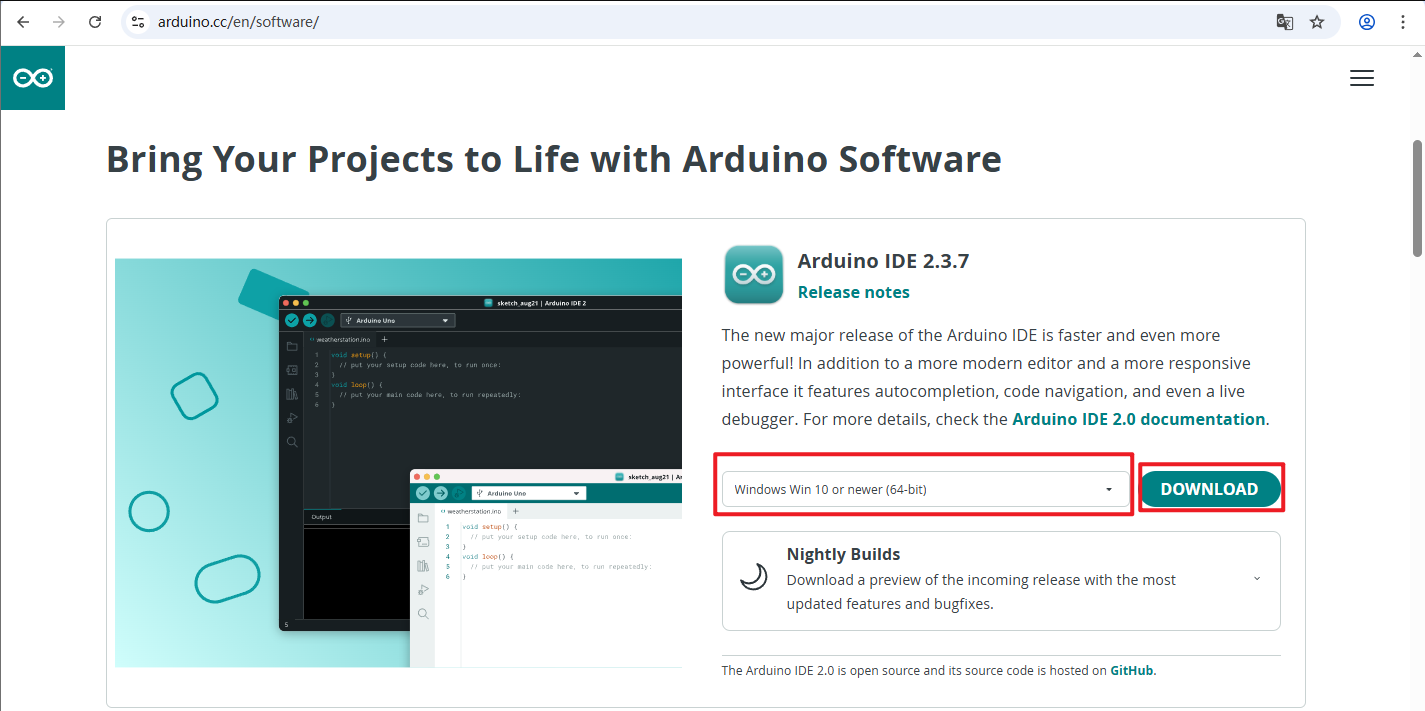
Follow the installation guide of Arduino software to proceed with the installation and download
Install the ESP32 development board
-
To use ESP32-related boards in the Arduino IDE, you must first install the "esp32 by Espressif Systems" development board software package
-
Install according to the board installation requirements
After opening the software
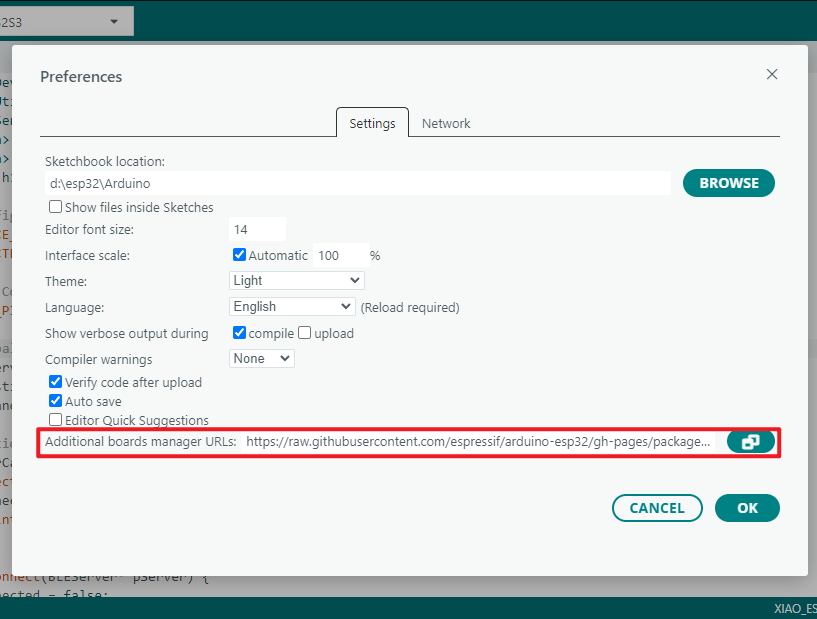
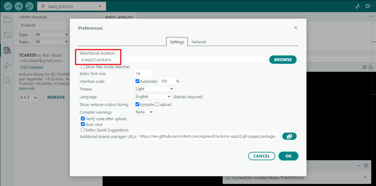
File - Preferences
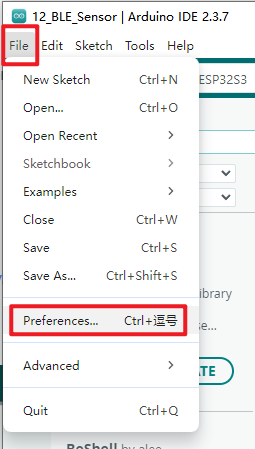
Add the address of the development board manager
https://raw.githubusercontent.com/espressif/arduino-esp32/gh-pages/package_esp32_index.json
Select "OK" after completion
Install the development board
-
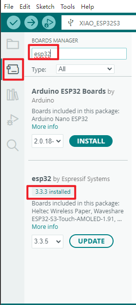
Select the Development Board Manager on the left side of the software
-
Search for "esp32" in the search bar
-
Select a version of the development board esp32 by Espressif Systems that is ≥3.2.0 in the version column found in the search results
-
Click to install
-
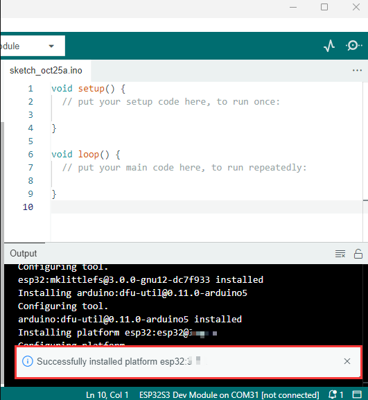
Clicking it will result in a similar prompt message appearing in the lower right corner of the software, indicating that the download is pending (please ensure a stable network connection while waiting for the download)

-
A successful prompt message will appear after the download is complete
-
The word "Installed" will appear when searching again

Install required libraries
When installing Arduino libraries, there are usually two options to choose from: `online installation` and `offline installation`.
If the library installation requires offline installation, the provided library file must be used. For most libraries, users can easily search and install them through the online library manager of the Arduino software.
However, some open-source libraries or custom libraries have not been synchronized to the Arduino library manager, and therefore cannot be obtained through online search.
In this case, users can only manually install these libraries through offline methods.
The W10 (LoRa AIOT Dev Kit) library file is stored in the example program. Click here to jump to it:
The library files that need to be downloaded for LoRa AIOT Dev Kit (DEVK1.0) W10 are:
| Database name | Instructions | Version | Library installation requirements |
|---|---|---|---|
| lvgl | LVGL graphical library | v8.4.0 | "Online" installation |
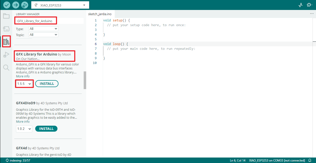
| GFX_Library_for_Arduino | GFX graphical library | v1.5.5 | "Online" installation |
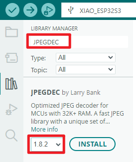
| JPEGDEC | JPG decoding library | v1.8.2 | "Online" installation |
| PNGdec | PNG decoding library | v1.1.3 | "Online" installation |
| XPowersLib | PNG decoding library | v0.2.9 | "Online" installation |
| SensorLib | PNG decoding library | v0.3.1 | "Online" installation |
| ESP32-audioI2S-master | Audio processing library | v3.3.0 | "Online" installation |
| Adafruit MCP23017 Arduino Library | Extended IO library | v2.3.2 | "Online" installation |
| es8311 | es8311 driver library | --- | "Online" installation |
Steps for downloading library files online:
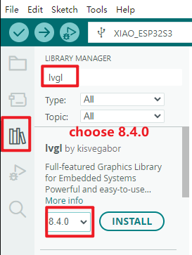
lvgl
-
Select "LIBRARY MANAGER" in the sidebar
-
Input the name of the library you want to install in the search box, such as **"lvgl"**
-
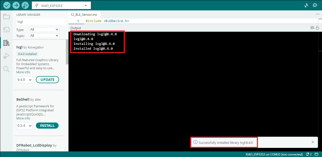
Select version 8.4.0 in the box
Installation successful
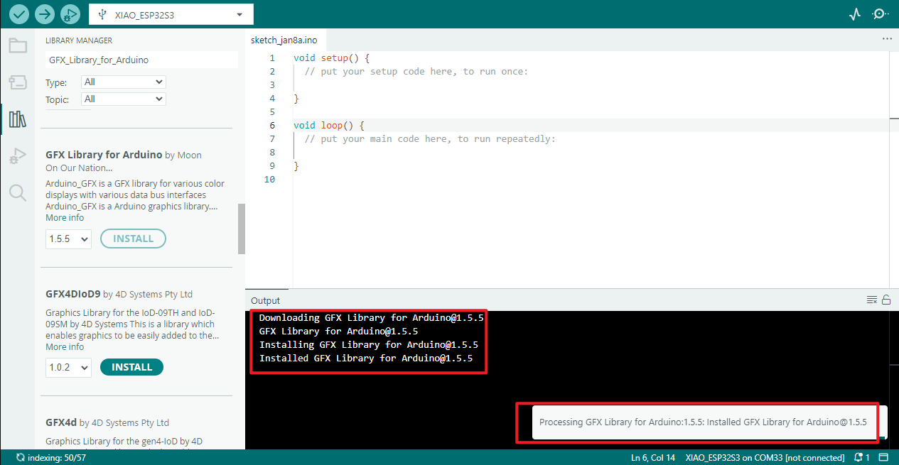
GFX_Library_for_Arduino
Select the corresponding version 1.5.5
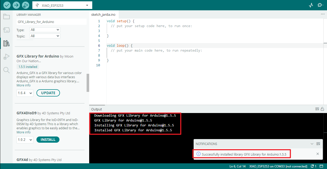
Installation process
Installation successful
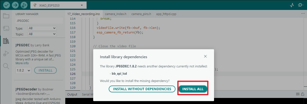
JPEGDEC
Select the corresponding version 1.8.2
The pop-up prompt message indicates that multiple dependencies need to be installed. Select "Install All"
Waiting for installation
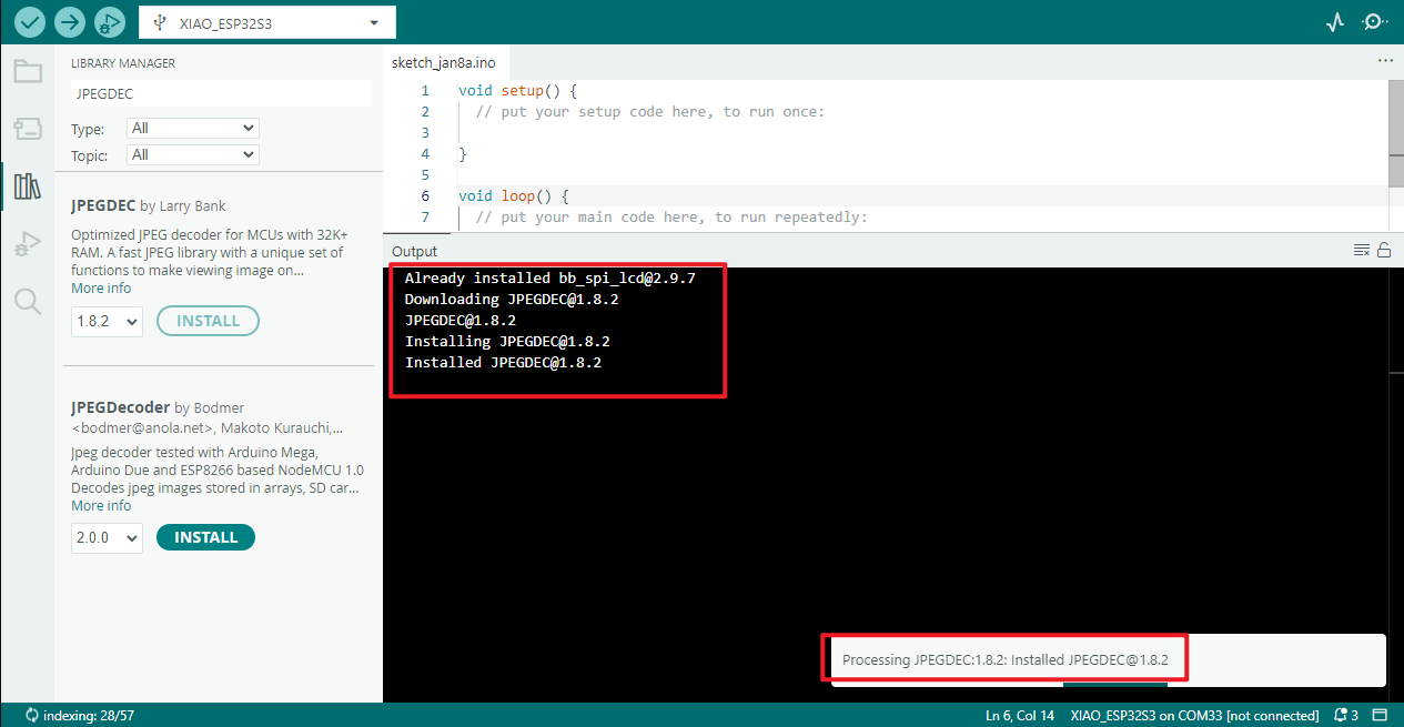
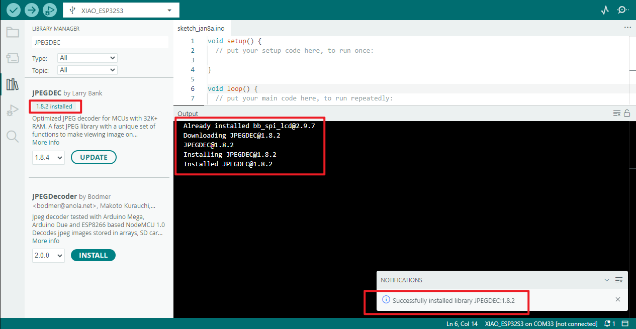
Installation successful
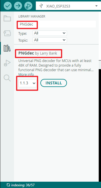
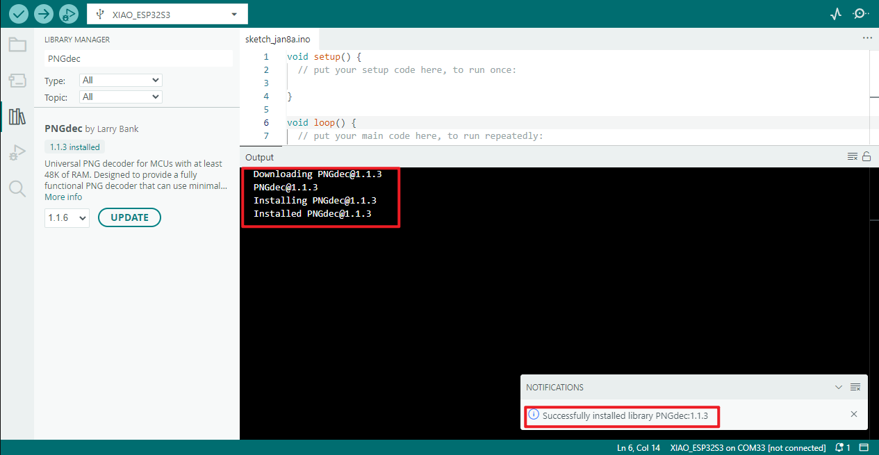
PNGdec
Select the corresponding version 1.1.3
Waiting for installation
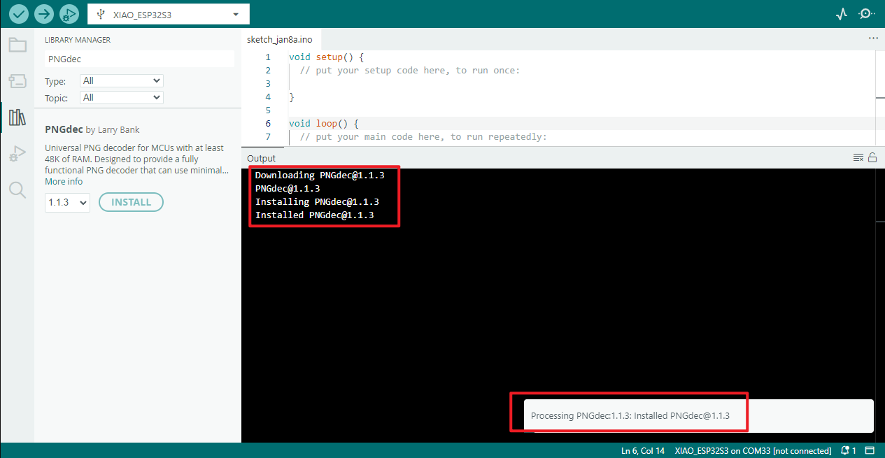
Installation successful
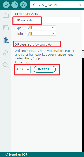
XPowersLib
Select the corresponding version 0.2.9
Waiting for installation
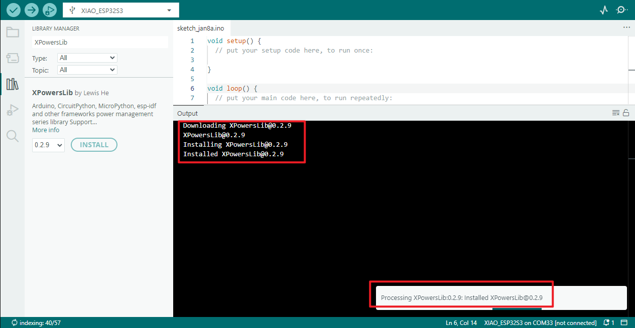
Installation successful

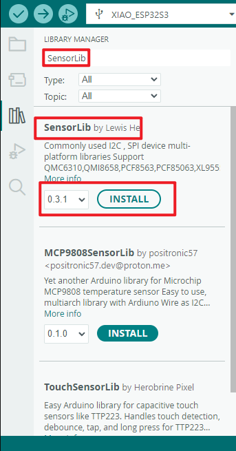
SensorLib
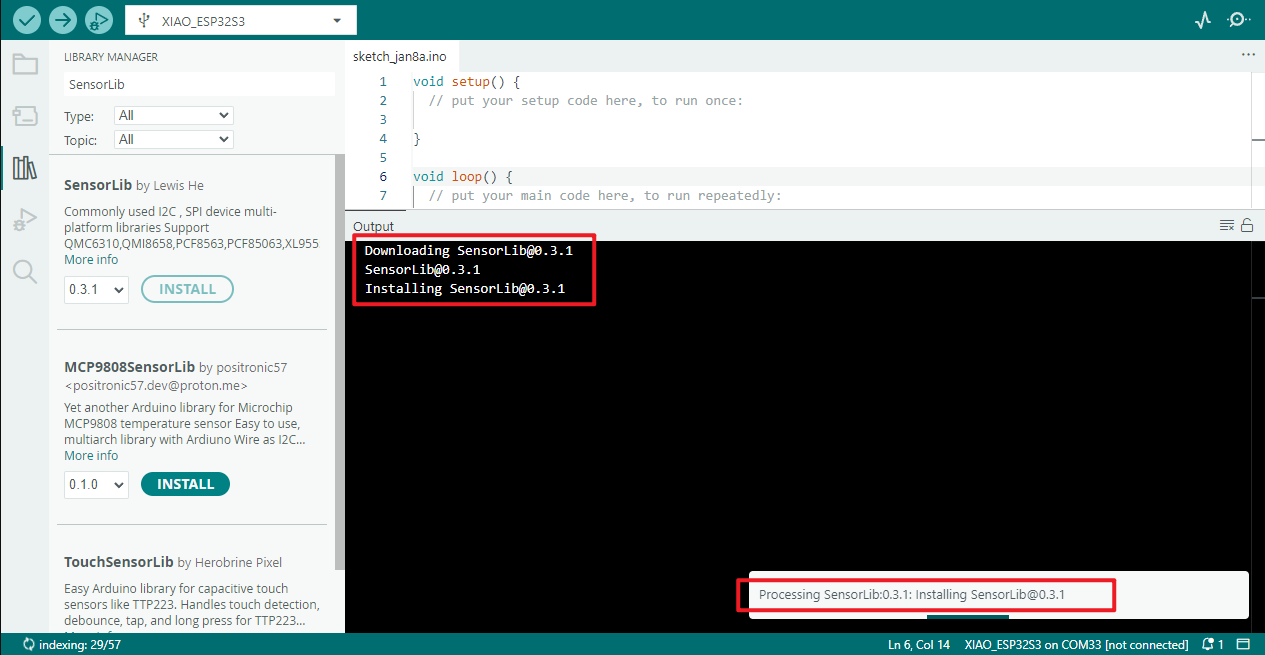
Select the corresponding version 0.3.1
Waiting for installation
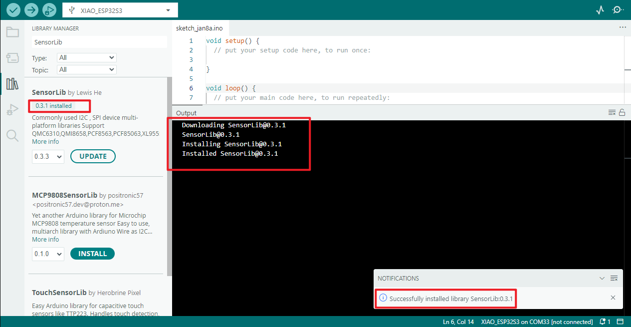
Installation successful
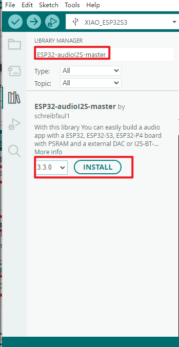
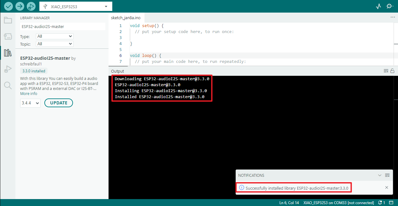
ESP32-audioI2S-master
Select the corresponding version 3.3.0
Waiting for installation
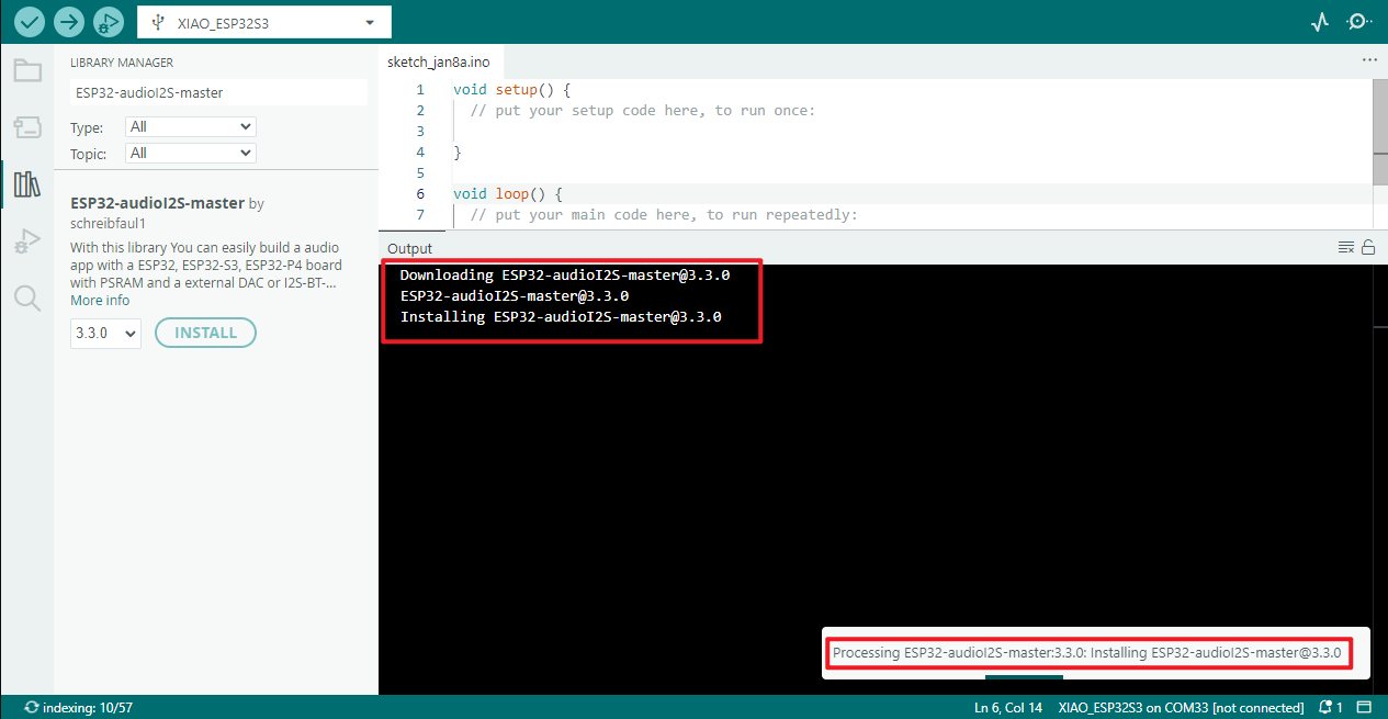
Installation successful
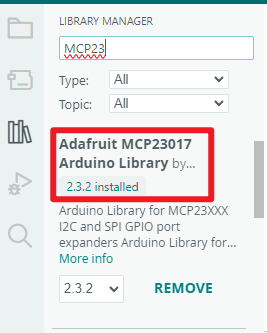
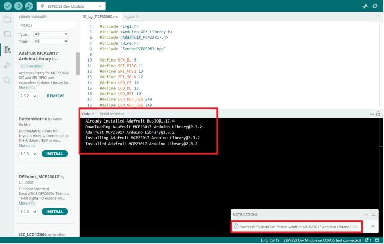
Adafruit MCP23017 Arduino Library
Select the corresponding version 2.3.2
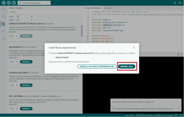 Waiting for installation
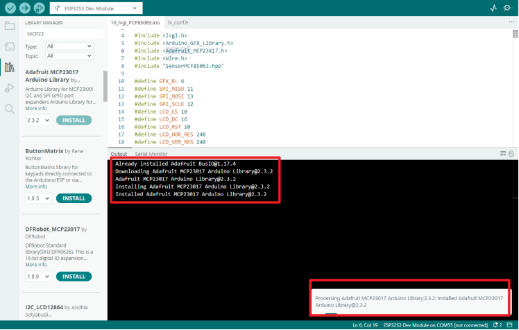 Installation successful
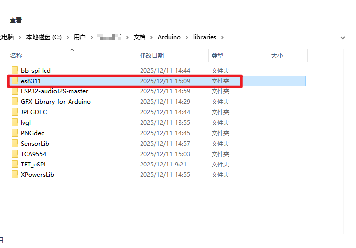
es8311
This package requires offline installation
First, download the library for es8311

Place this downloaded library file in the Arduino software library file storage location
Default storage location:
C:\Users(Username)\Documents\Arduino\libraries
If your location has changed, you can view the location information on your computer through the software
Instance program
All instances come with source code and pre-packaged bin files, which can be directly programmed using the flash_download_tool or through an online web page。
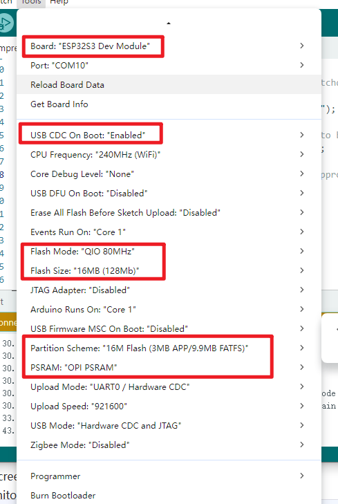
- LoRa AIOT Dev Kit Engineering Parameter Configuration
The parameters must be configured according to the information shown in the image for the firmware to be flashed correctly.
01_Drive AXP2101
Program Description
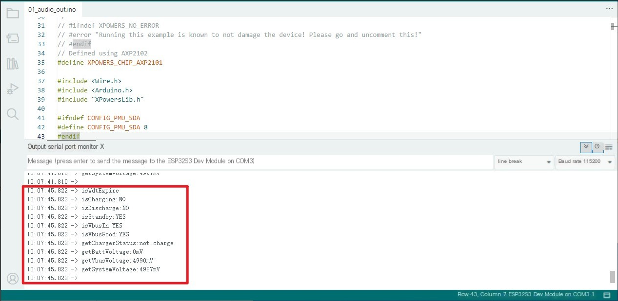
- Real-time printing of the working status of AXP2101 PMU, including charging/discharging/standby, as well as VBUS/battery/system voltage and remaining battery capacity
Hardware connection
- Connect the board to the computer using a USB cable
Operating effect
-
No abnormality on the screen
-
Open the serial port monitor (Baud rate 115200)
02_Drive ES8311
Program Description
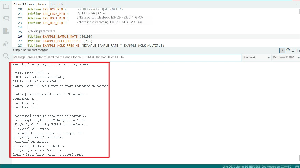
- This example demonstrates the use of the LoRa AIOT Dev Kit (W10) to drive the ES8311 audio codec, enabling audio recording and playback functions.
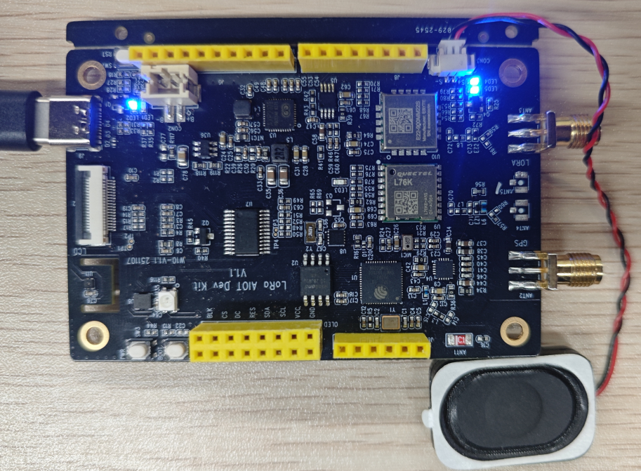
Hardware connection
-
Connect the board to the computer using a USB cable
-
Connect CON3 port to the speaker
Operating effect
-
After the programming is completed, press "boot" to record a 5-second sound, and then play it
-
Open the serial port monitor (Baud rate 115200)
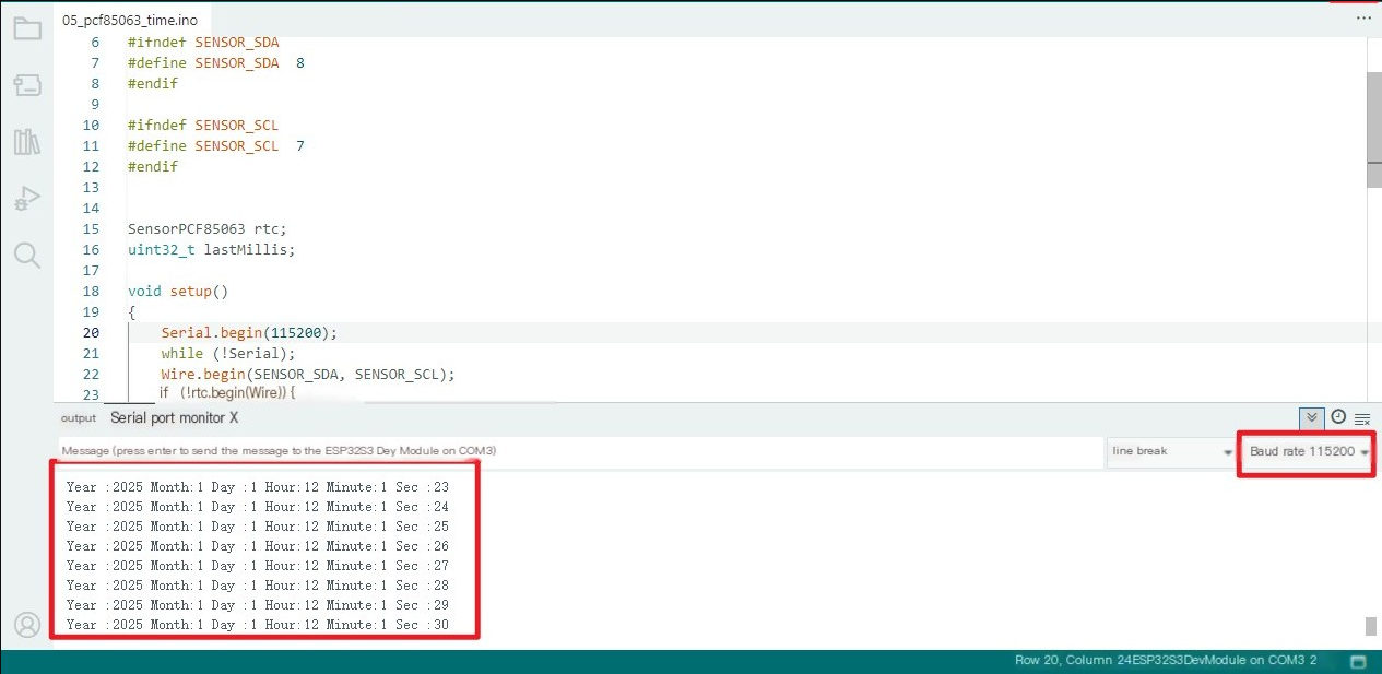
03_Drive PCF85063
Program Description
● Drive PCF85063, set time and date, and obtain time
Hardware connection
Connect the board to the computer using a USB cable
Operating effect
● No abnormality on the screen
● Open the serial port monitor (Baud rate 115200)
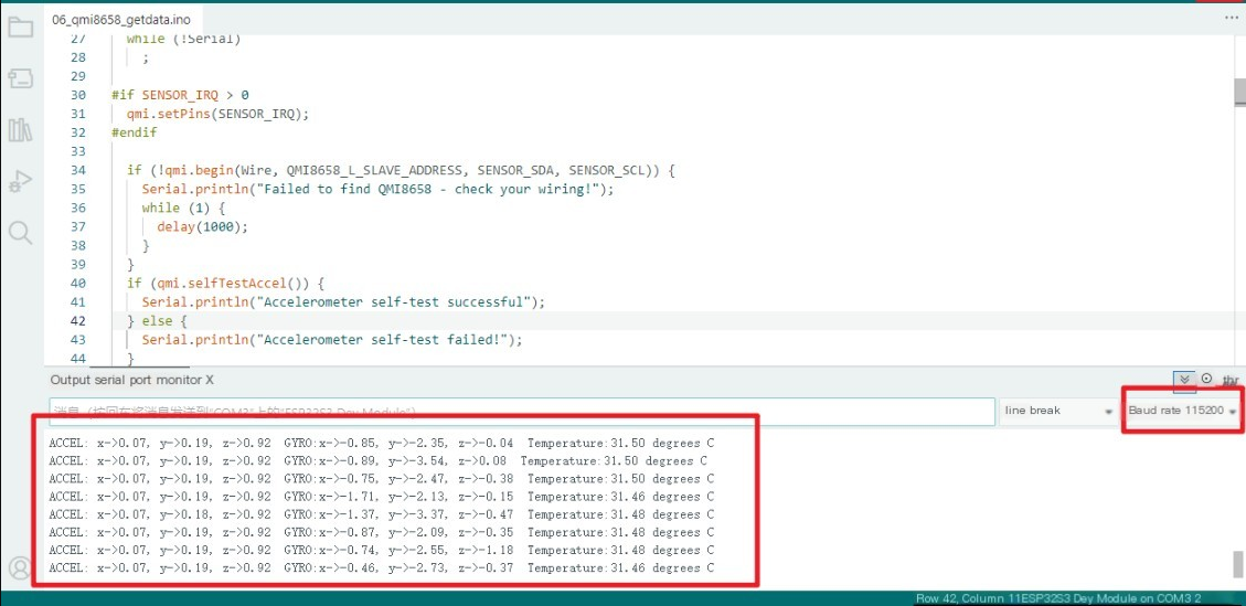
04_Drive QMI8658
Program Description
- Drive QMI8658 to obtain and print the temperatures of Accel, Gyro, and IMU
hardware connection
- Connect the board to the computer using a USB cable
operating effect
-
No phenomenon on the screen
-
Open the serial port monitor
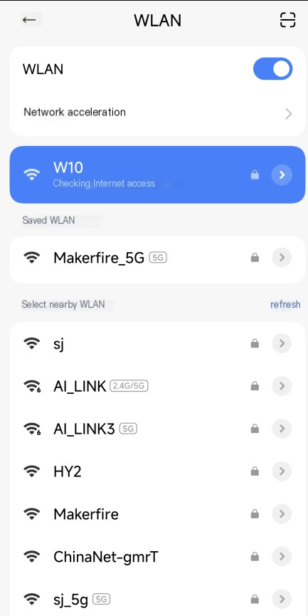
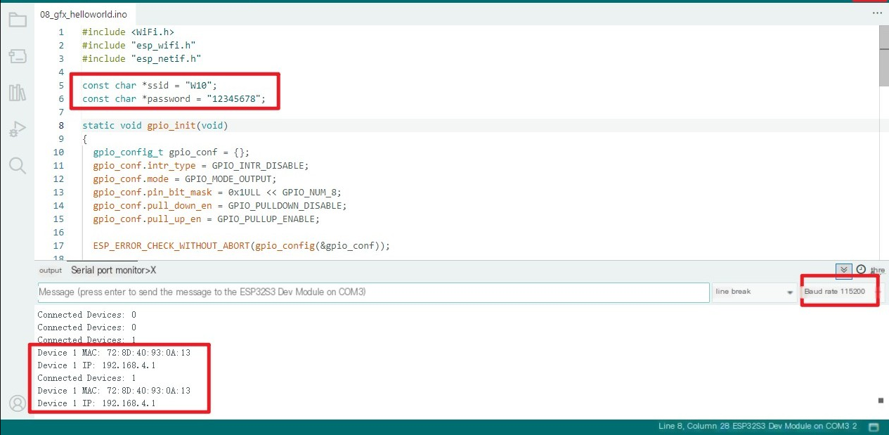
05_WIFI_AP
Program Description
- This example allows the development board to be set as a hotspot, enabling mobile phones or other devices in STA mode to connect to the development board
const char *ssid = "W10";
const char *password = "12345678";
SSID: The correspondingly set WiFi name
password: The corresponding WiFi password set
Hardware connection
- Connect the board to the computer using a USB cable
Operating effect
- After programming, open the serial terminal. If the mobile phone or computer device successfully connects to the hotspot, the MAC address of the device will be output
Mobile screenshot:
Serial port monitor status
06_WIFI_STA
Program Description
-
This example allows the development board to be configured as an STA device, enabling it to connect to a router and thereby access the system network
-
Find the ssid and password in the 07_WIFI_STA.ino file, and then modify them to the SSID and Password of the router available in the current environment.
const char *ssid = "you_ssid";
const char *password = "you_password";
Hardware connection
- Connect the board to the computer using a USB cable
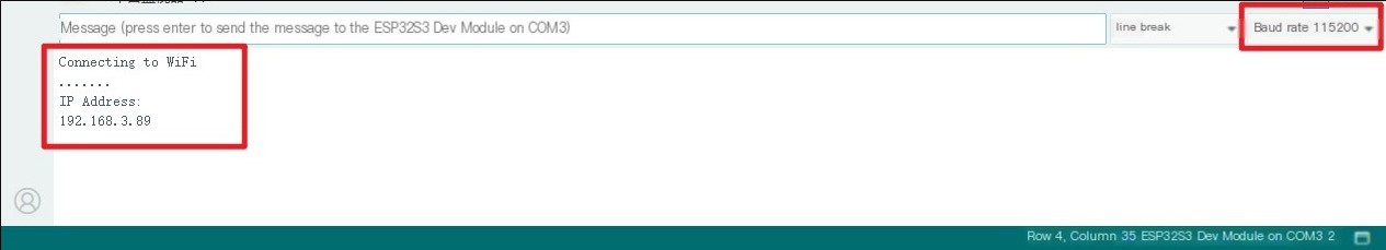
Operating effect
- After programming, open the serial terminal. If the device successfully connects to the hotspot, it will output the obtained IP address, as shown in the figure:
07_Driver for Quectel_L76K
Program Description
-
This example can drive the L76K device of the development board
-
Output information such as UTC (Coordinated Universal Time), latitude and longitude, positioning quality, number of satellites, horizontal dilution of precision, and altitude in sequence
Hardware connection
-
Connect the board to the computer using a USB cable
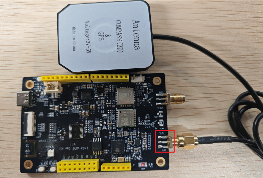
-
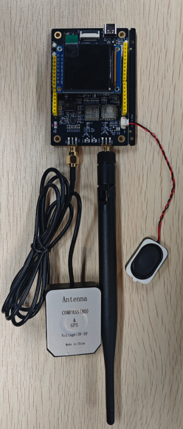
Connect the equipped GPS antenna to the ANT2 interface of the board, and the effect is shown in the figure below:
Operating effect
-
After programming, open the serial terminal
-
If the operating environment is indoors and GPS cannot receive information, the output effect of the serial port terminal will be
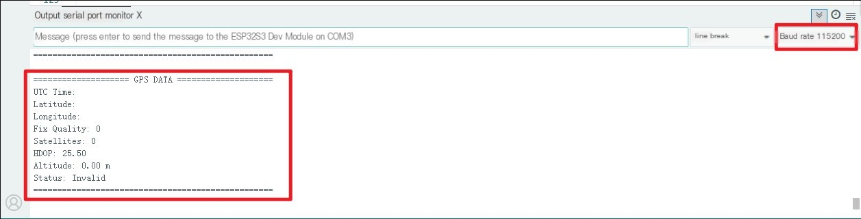
-
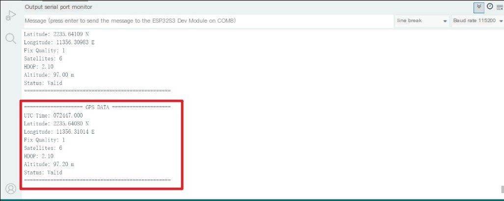
If the operating environment is outdoors and GPS can receive information normally, the output effect of the serial port terminal will be
-
The current latitude and longitude format is NMEA format.
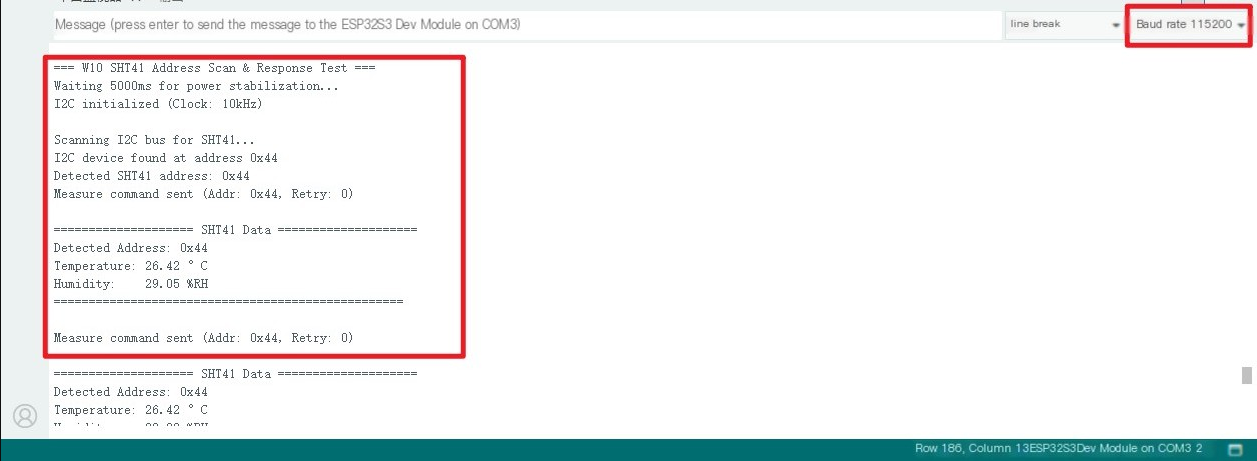
08_Drive SHT41_getdata
Program Description
● Initialize the SHT41 chip through the I2C protocol, and then print the temperature and humidity information read every 3 seconds to the terminal
Hardware connection
● Connect the board to the computer using a USB cable
Operating effect
● Open the serial port monitor to view the temperature and humidity data printed out, as shown in the figure below:
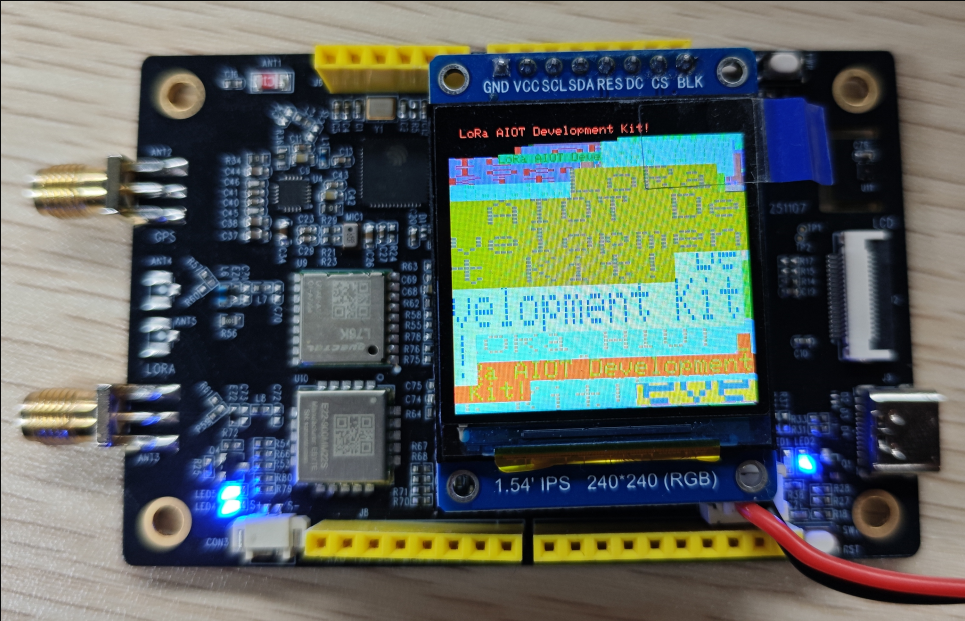
09_gfx_LoRa AIOT Development Kit!
Program Description
- This program drives the LCD1.54 screen, displaying "LoRa AIOT Development Kit" on it! and other information
Hardware connection
-
Connect the board to the computer using a USB cable
-
Connect the 1.54-inch LCD screen to the OLED J4 interface of the board
Operating effect
- After successfully uploading the program, you need to press the RST button on the board to see the displayed text
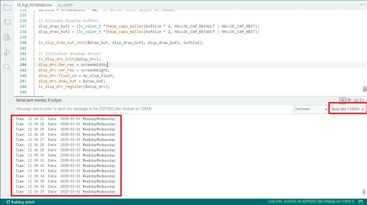
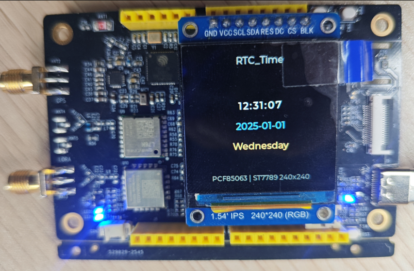
10_lvgl_PCF85063
Program Description
- This example demonstrates how to use the W10(LoRa AIOT Dev Kit) to obtain the time and date data of the PCF85063 and display it through the lvgl library.
Hardware connection
-
Connect the board to the computer using a USB cable
-
Connect the 1.54-inch LCD screen to the OLED J4 interface of the board
Operating effect
- Serial port monitor:
Board status:
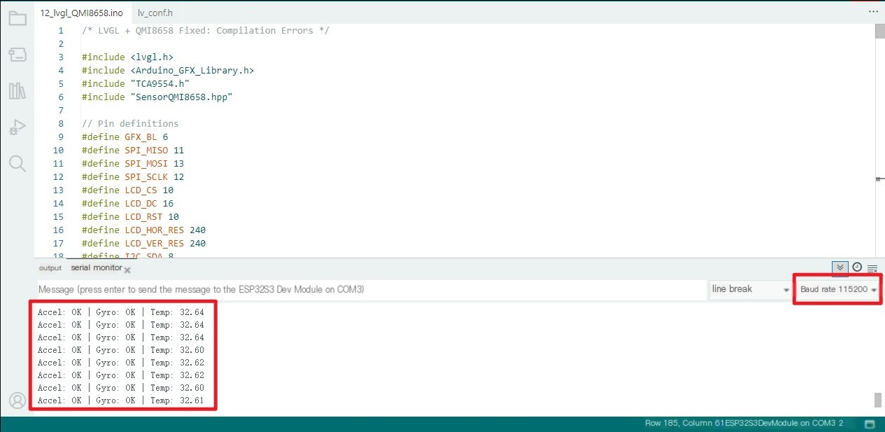
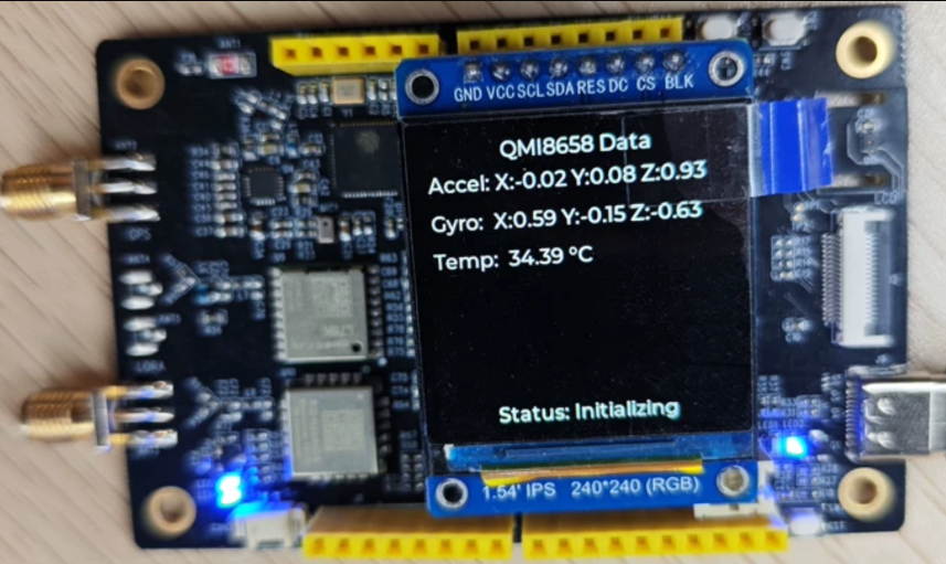
11_lvgl_QMI8658
Program Description
This example demonstrates the use of W10 (LoRa AIOT Dev Kit) to obtain data from qmi8658 and display it through the lvgl library.
Hardware connection
-
Connect the board to the computer using a USB cable
-
Connect the 1.54-inch LCD screen to the OLED J4 interface of the board
Operating effect
Serial port monitor:
Board status:
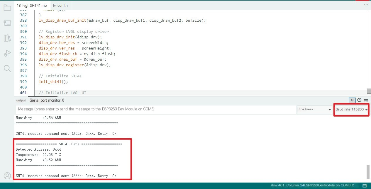
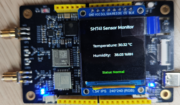
12_lvgl_SHT41
Program Description
This example demonstrates the use of W10 (LoRa AIOT Dev Kit) to obtain data from qmi8658 and display it through the lvgl library.
Hardware connection
-
Connect the board to the computer using a USB cable
-
Connect the 1.54-inch LCD screen to the OLED J4 interface of the board
Operating effect
Serial port monitor:
Board status:
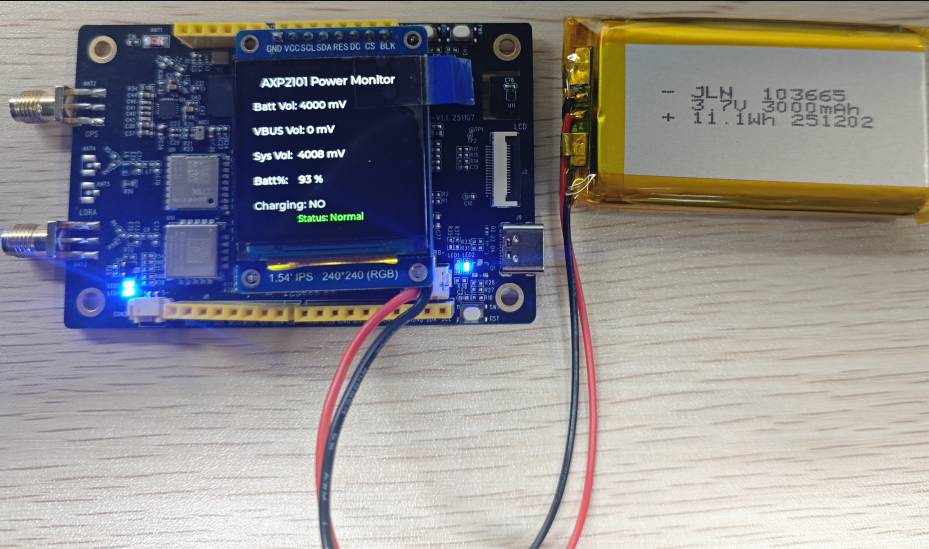
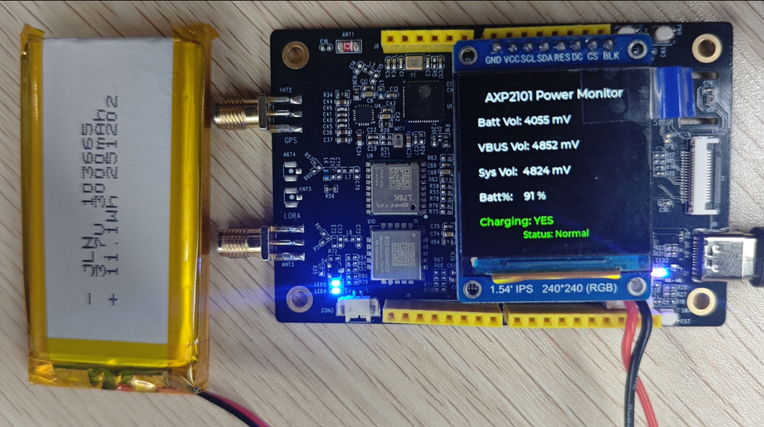
13_lvgl_AXP2101
Program Description
This example demonstrates the use of W10 (LoRa AIOT Dev Kit) to obtain data from axp2101 and display it through the lvgl library.
Data Description
| Numerical name | Meaning | Normal range |
|---|---|---|
| Battery Voltage | Battery voltage (lithium battery) | 3000 |
| VBUS Voltage | VBUS input voltage (external power supply, such as USB/adapter) | 4000 |
| System Voltage | System output voltage (voltage supplied by AXP2101 to the main controller/peripherals) | Determined by the configured DC/ALDO/BLDO |
| Battery Percent | Percentage of battery remaining | 0~100 % |
| Charging | Battery charging status | YES = charging, NO = not charging |
Hardware connection
-
Connect the board to the computer using a USB cable
-
Connect the 1.54-inch LCD screen to the OLED J4 interface of the board
-
Connect the lithium battery to the CON3 interface
Operating effect
Only lithium batteries:
Lithium battery + USB:
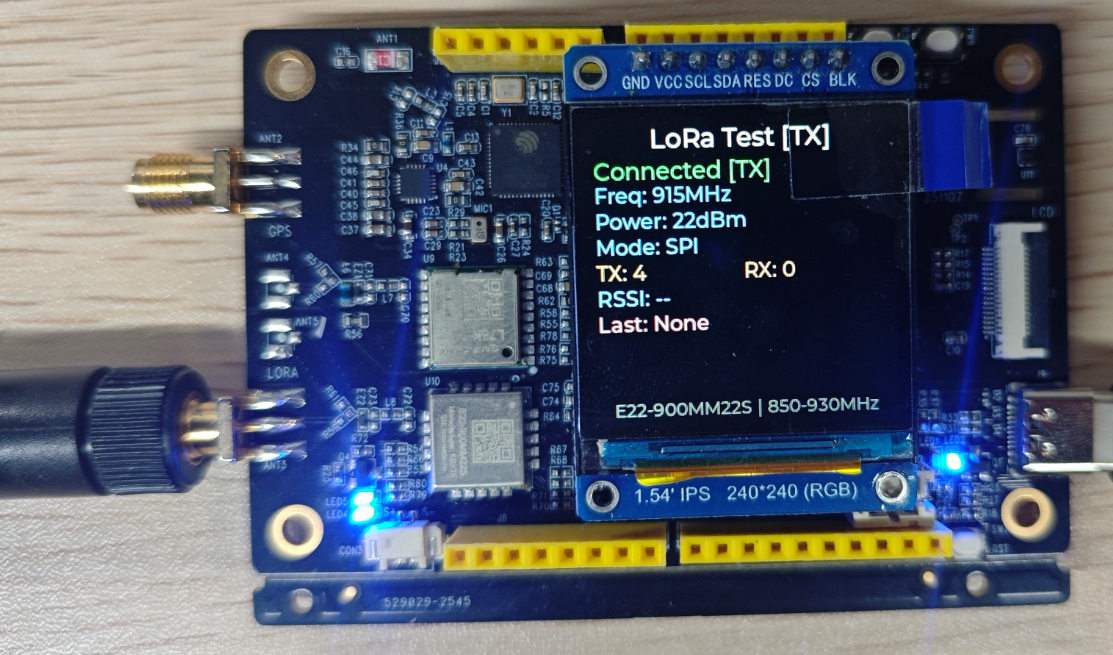
14_lvgl_LoRa
Program Description
This example demonstrates the use of W10 (LoRa AIOT Dev Kit) to obtain data from E22-900MM22S (LoRa) and display it through the lvgl library.
Hardware connection
-
Connect the board to the computer using a USB cable
-
Connect the 1.54-inch LCD screen to the OLED J4 interface of the board
-
Antenna connected to ANT3 LoRa interface
Operating effect
Single module test: (one device)
-
Check whether the module status is "Connected"
-
Check whether the parameters (frequency, power, mode) are displayed correctly
-
Check whether the TX count increases when sending messages
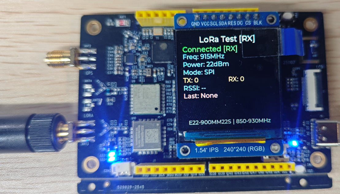
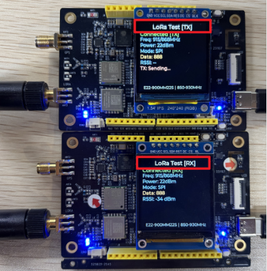
Dual-module test: (two devices)
-
One device is in TX mode, while the other is in RX mode
-
Check whether the module status is "Connected"
-
Check whether the parameters (frequency, power, mode) are displayed correctly
-
Check whether the RX count increases when sending messages
-
Check Last: Whether data from 111-999 will be displayed
Mode switching: When pressing RST for reset, entering TX mode without pressing the Boot button; when pressing RST for reset, entering RX mode by holding down the Boot button
15_comprehensiv_example
Program Description
This example demonstrates the use of W10 (LoRa AIOT Dev Kit) to test whether various devices are functioning properly. It displays IMU, GPS, RTC, and Temp/Hum data on the main page.
Short-pressing the boot button on the main page enters LoRa's TX transmission mode, while long-pressing the boot button enters LoRa's RX reception mode, and the display is managed through the lvgl library.
Hardware connection
-
Connect the board to the computer using a USB cable
-
Connect the 1.54-inch LCD screen to the OLED J4 interface of the board
-
Antenna connected to ANT3 LORA interface
Operating effect
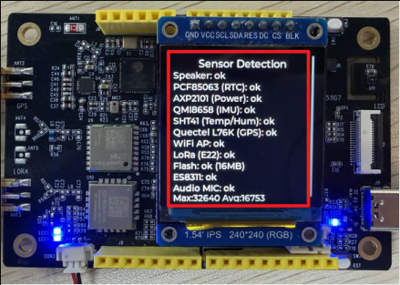
Upon programme initiation, the connected display will first present the Sensor Detection interface.
This interface serves to verify the functionality of all peripheral devices.
Speaker: Audio output functionality; upon connection, the speaker will emit three beeps (Speaker: Testing...) indicating normal operation (Speaker: ok).
Subsequent checks will detect each peripheral (Detecting...), displaying “ok” for successful detection or “Failed” for unsuccessful detection.
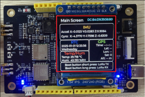
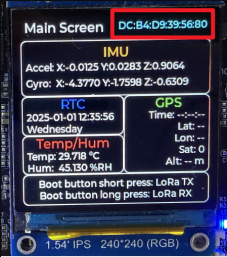
After approximately 20 seconds, the display will transition to the Main Screen interface.
This interface displays information for switching between the device's STA ID, IMU, RTC, Temp/Hum, GPS, and LoRa interfaces.
Correct data display interface:
Indoor (no GPS information, as indoor GPS cannot receive satellite data):
Outdoor open locations (with GPS information), powered by battery or USB:
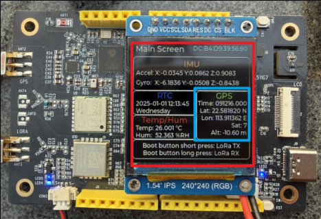
This ID on the interface corresponds to each device's STA address, which can be matched with the STA address on the programming tool:
 |  |
|---|
LoRa Functional testing:
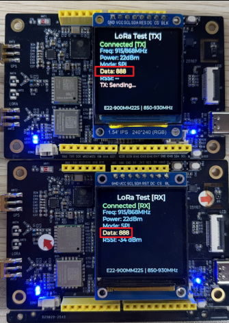
📌To view received messages via LoRa, one device must be in transmit mode and another in receive mode (with antennas operating on the same frequency band).
On the Main Screen interface, briefly press the BOOT button to enter LoRa TX (transmit mode).
On the Main Screen interface, briefly press the BOOT button to enter LoRa RX (receive mode).
After entering separately, the Data displayed on both boards' screens is identical, indicating successful transmission and reception of data.
In the LoRa Test[TX] interface, briefly press the Boot button to switch to the Main Screen interface and continue displaying data.
In the LoRa Test[RX] interface, briefly press the Boot button to switch to the LoRa Test[TX] interface. In the LoRa Test[TX] interface, briefly press the Boot button again to switch to the Main Screen interface.