W12 LR2021 Ultra Long Range LoRa Device
Product Overview
Description:
The LR2021 Ultra Long Range LoRa Device is an upgraded version of the Heltec WiFi LoRa 32 V4, designed as a multi-mode communication development board. At its core is an ESP32-S3R8 dual-core MCU (240MHz clock speed, 8MB PSRAM + 16MB Flash), featuring the fourth-generation LR2021 LoRa communication chip (LoRa up to 125 kbps, FLRC up to 2.6 Mbps), and equipped with a 0.96-inch yellow-and-blue dual-colour OLED display.
It supports WiFi 4 + BLE 5.0 + LoRa full-band communication, with a LoRa transmission power of up to 30dBm and a reception sensitivity of -142dBm, offering a 20–30% increase in communication range compared to V4; The battery management chip has been optimised to support solar panels operating at 4.5–24 V, with an industrial-grade temperature range of –40 °C to 85 °C, ensuring it can operate in extreme environments.
Product images:
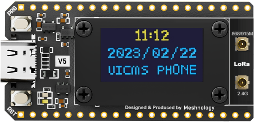
If you’d like to view the 3D renderings, please click the link.
Product Features
The WiFi LoRa 32 V5 is a high-performance wireless communication development board designed for IoT developers, enterprise-level IoT projects and outdoor monitoring applications. Building on the ‘WiFi+BLE+LoRa’ multi-mode communication capabilities of the V4 version, it features upgraded core components (ESP32-S3R8 MCU + LR2021 LoRa chip), enhanced hardware configuration, optimised low-power design and expanded scenario-specific interfaces, it achieves product characteristics of “greater communication range, higher computational efficiency, stronger environmental adaptability and more flexible scenario expansion”. It is suitable for scenarios with high demands for communication stability, battery life and computing power, such as LoRaWAN gateways, mesh networks, outdoor environmental monitoring, smart agriculture and industrial IoT (IoT).
Technical Specifications
Hardware specifications
| Category | Parameter items | Specific technical specifications |
|---|---|---|
| central processing unit | Chip model | ESP32-S3R8 (dual-core 32-bit LX7 microprocessor) |
| Main frequency | Up to 240 MHz | |
| On-board SRAM | 512KB | |
| Built-in PSRAM | 8 MB (supports high-resolution image caching and multi-task data storage) | |
| Key features | Hardware floating-point operations, vector instruction sets, neural network accelerators (NPUs, supporting AI inference at INT8/FP16 precision) | |
| Storage configuration | On-board Flash | 16MB SPI NOR Flash (supports OTA firmware updates and firmware encryption) |
| Support for expandable storage | SPI interface expansion, compatible with SD cards up to 128GB | |
| WiFi & Bluetooth wireless connectivity | Wi-Fi standards / bands | Wi-Fi 4, 802.11b/g/n, 2.4 GHz band |
| Wi-Fi data transfer rate / range | Up to 150 Mbps, indoor range ≥ 50 m, outdoor range ≥ 100 m (packet loss rate ≤ 1% at 100 m) | |
| Wi-Fi mode / Security protocol | Station/SoftAP/ Hybrid mode; supports WPA3/WPA2-PSK | |
| Bluetooth version / mode | Bluetooth 5.0, supporting BLE (Bluetooth Low Energy), Classic Bluetooth and Bluetooth Mesh networks | |
| Bluetooth transmission speed / range | Up to 2 Mbps; BLE: 32 m indoors; Long-range mode: ≥1 km in open terrain | |
| LoRaFeatures | LoRa device | Semtech’s fourth-generation high-performance LoRa RF transceiver, the LR2021 |
| Frequency range | 150 - 960MHz and 1.5 - 2.5GHz bands、 | |
| Modulation method | LoRa®, (G)(M)FSK, OOK, O-QPSK, FLRC or LR-FHSS. | |
| Maximum transmit power | 30±1dbm,24±1dbm | |
| Receiver sensitivity | -142dBm @ LoRa SF12 125 kHz Sub-1G | |
| LoRa antenna | On-board Sub-1 GHz and 2.4 GHz IPEX sockets | |
| Input and output interfaces | GPIO pins | Up to 32 reusable GPIO pins (all supporting interrupt triggering: rising edge / falling edge / both edges) |
| ADC channel | 20 channels, 12-bit resolution, input range 0–3.3 V | |
| SPI interface | 3 channels (1 high-speed SPI channel at 40 MHz for PSRAM/Flash, and 2 general-purpose SPI channels for peripheral expansion) | |
| UART interface | 3 channels, maximum baud rate 2 Mbps (supports hardware flow control) | |
| Antenna socket | 3 lanes IPEX1.0 ANT(LoRa Sub-1G、LoRa 2.4G、WiFi&BT 2.4G) | |
| Other key interfaces | 2-channel I2S (audio input/output), 8-channel PWM, 1-channel USB Type-C (data/power/programming) | |
| Additional feature interfaces | Solar panel connector (4.5–24 V), lithium battery connector (3.7 V), user buttons (reset / custom), RGB LED (status indicator) | |
| OLED | Dimensions | 0.96-inch, 128×64 resolution, yellow and blue dual-colour OLED |
| driver chip | SSD1315 | |
| Power management | Power supply method | 1. USB Type-C (5V/1A); />2. Solar panel (4.5–24V/1A); 3. Lithium battery (3.3V–4.2V, 300mAh–5000mAh); 4. External DC power supply (3.3V–5V/1A peak) |
| Charging management | Adjustable charging current (up to 4A) with LED charging status indicator; features overcharge, over-discharge, overcurrent and short-circuit protection | |
| Power consumption (typical) | Active mode: ≤120 mA; Sleep mode: ≤15 mA; Standby mode: ≤8 µA; Power-down mode: ≤1 µA | |
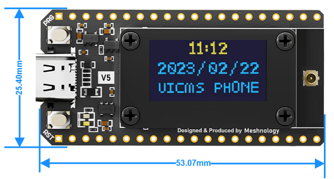
| Physical properties | Dimensions | 53.07 × 25.4mm × 15.6mm |
| weight | 12g | |
| PCB Specifications | 1.6 mm thick FR-4 board, gold-plated process | |
| Environmental characteristics | Operating temperature range | -40°C to 85°C (industrial grade); OLED temperature range (-40°C to 70°C) |
| Storage temperature range | -40℃~125℃ | |
| Operating humidity | 10%~90% RH(No condensation) |
Hardware pins
1.1.1 Hardware Pin Definitions
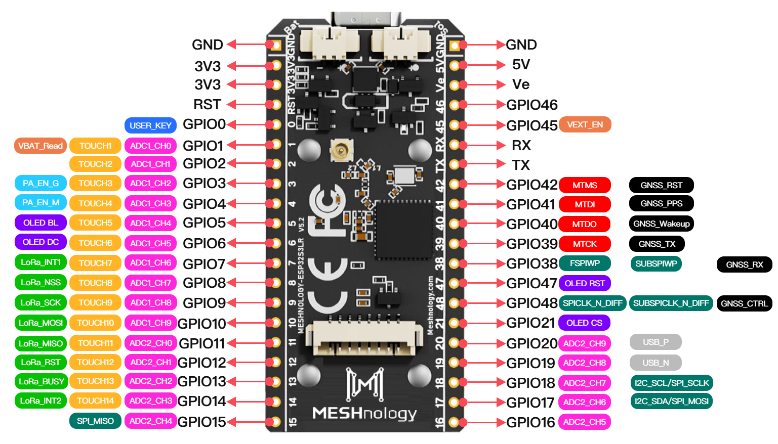
1、Expanded I/O ports: from the bottom left to the top left
| No. | Name | Type | Function |
|---|---|---|---|
| 1 | GND | G | Ground |
| 2 | 3V3 | P | 3.3V Power Supply |
| 3 | 3V3 | P | 3.3V Power Supply |
| 4 | RST | I | CHIP_PU, RST_KEY |
| 5 | IO0 | I/O, IO MUX | GPIO0, USER_KEY |
| 6 | IO1 | I/O, Analog, RTC, IO MUX | GPIO1, ADC1_CH0, TOUCH1, VBAT_Read |
| 7 | IO2 | I/O, Analog, RTC, IO MUX | GPIO2, ADC1_CH1, TOUCH2 |
| 8 | IO3 | I/O, Analog, RTC, IO MUX | GPIO3, ADC1_CH2, TOUCH3, PA_EN_G |
| 9 | IO4 | I/O, Analog, RTC, IO MUX | GPIO4, ADC1_CH3, TOUCH4, PA_EN_M |
| 10 | IO5 | I/O, Analog, RTC, IO MUX | GPIO5, ADC1_CH4, TOUCH5, OLED BL |
| 11 | IO6 | I/O, Analog, RTC, IO MUX | GPIO6, ADC1_CH5, TOUCH6, OLED DC |
| 12 | IO7 | I/O, Analog, RTC, IO MUX | GPIO7, ADC1_CH6, TOUCH7, LoRa_INT1 |
| 13 | IO8 | I/O, Analog, RTC, IO MUX | GPIO8, ADC1_CH7, TOUCH8 LoRa_NSS |
| 14 | IO9 | I/O, Analog, RTC, IO MUX | GPIO9, ADC1_CH8, TOUCH9 LoRa_SCK |
| 15 | IO10 | I/O, Analog, RTC, IO MUX | GPIO10, ADC1_CH9, TOUCH10 LoRa_MOSI |
| 16 | IO11 | I/O, Analog, RTC, IO MUX | GPIO11, ADC2_CH0, TOUCH11 LoRa_MISO |
| 17 | IO12 | I/O, Analog, RTC, IO MUX | GPIO12, ADC2_CH1, TOUCH12 LoRa_RST |
| 18 | IO13 | I/O, Analog, RTC, IO MUX | GPIO13, ADC2_CH2, TOUCH13 LoRa_BUSY |
| 19 | IO14 | I/O, Analog, RTC, IO MUX | GPIO14, ADC2_CH3, TOUCH14, LoRa_INT2 |
| 20 | IO15 | I/O, Analog, RTC, IO MUX | GPIO15, XTAL_32K_P, ADC2_CH4, SPI_MISO |
| 21 | IO16 | I/O, Analog, RTC, IO MUX | GPIO16, XTAL_32K_N, ADC2_CH5 |
| 22 | IO17 | I/O, Analog, RTC, IO MUX | GPIO17, ADC2_CH6, I2C_SDA/SPI_MOSI |
| 23 | IO18 | I/O, Analog, RTC, IO MUX | GPIO18, ADC2_CH7, I2C_SCL/SPI_SCLK |
| 24 | IO19 | I/O, Analog, RTC, IO MUX | GPIO19, U1RTS, ADC2_CH8, USB_N |
| 25 | IO20 | I/O, Analog, RTC, IO MUX | GPIO20, U1CTS, ADC2_CH9, USB_P |
| 26 | IO21 | I/O, RTC, IO MUX | GPIO21, OLED CS |
| 27 | IO48 | I/O, IO MUX | GPIO48, SPICLK_N_DIFF, SUBSPICLK_N_DIFF, GNSS_CTRL |
| 28 | IO47 | I/O, IO MUX | GPIO47, SPICLK_P_DIFF, SUBSPICLK_P_DIFF, OLED RST |
| 29 | IO38 | I/O, IO MUX | GPIO38, FSPIWP, SUBSPIWP, GNSS_RX |
| 30 | IO39 | I/O, IO MUX | GPIO39, MTCK, GNSS_TX |
| 31 | IO40 | I/O, IO MUX | GPIO40, MTDO, GNSS_Wakeup |
| 32 | IO41 | I/O, IO MUX | GPIO41, MTDI, GNSS_PPS |
| 33 | IO42 | I/O, IO MUX | GPIO42, MTMS, GNSS_RST |
| 34 | TX | I/O, IO MUX | GPIO43, U0TXD |
| 35 | RX | I/O, IO MUX | GPIO44, U0RXD |
| 36 | IO45 | I/O, IO MUX | GPIO45, VEXT_EN |
| 37 | IO46 | I/O, IO MUX | GPIO46 |
| 38 | Ve | P | Output 3.3V |
| 39 | 5V | P | 5V Power Supply |
| 40 | GND | G | Ground |
2、LR2021 chip: Main pin definitions
| No. | Name | Type | Function |
|---|---|---|---|
| 10 | IO7 | I/O, IO MUX | GPIO7, LORA_INT |
| 20 | IO12 | I/O, IO MUX | GPIO12, LORA_RESET |
| 21 | IO11 | I/O, IO MUX | GPIO11, LORA_MISO |
| 22 | IO10 | I/O, IO MUX | GPIO10, LORA_MOSI |
| 23 | IO9 | I/O, IO MUX | GPIO9, LORA_SCK |
| 24 | IO8 | I/O, IO MUX | GPIO8, LORA_NSS |
| 25 | IO13 | I/O, IO MUX | GPIO13, LORA_BUSY |
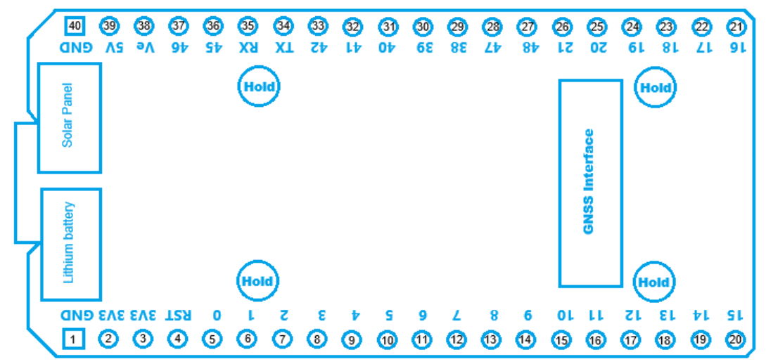
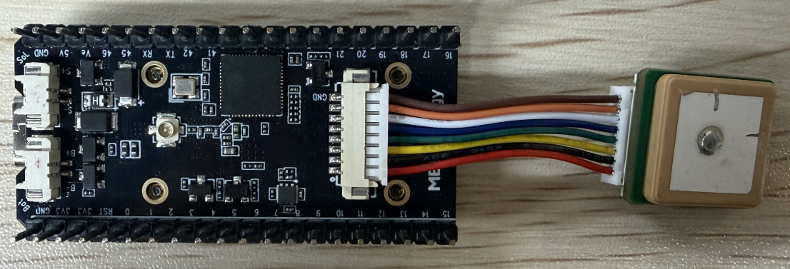
3、GNSS interface: from top to bottom
| No. | Name | Type | Function |
|---|---|---|---|
| 1 | GND | P | Ground |
| 2 | IO48 | I/O, IO MUX | 3.3V Power Output controlled by GNSS_CTRL |
| 3 | 3V3 | P | 3.3V Power Output for GNSS module |
| 4 | IO39 | I/O, IO MUX | GPIO39, MTCK, GNSS_TX |
| 5 | IO38 | I/O, IO MUX | GPIO38, FSPIWP, SUBSPIWP, GNSS_RX |
| 6 | IO40 | I/O, IO MUX | GPIO40, MTDO, GNSS_WKUP |
| 7 | IO41 | I/O, IO MUX | GPIO41, MTDI, GNSS_PPS |
| 8 | IO42 | I/O, IO MUX | GPIO42, MTMS, GNSS_RST |
4、Display interface: Arranged according to the pin configuration of the HC-PBB40C-20DP-0.4V-02 connector
| No. | Name | Type | Function |
|---|---|---|---|
| 1 | GND | P | Ground |
| 2 | 3V3 | P | 3.3V Power Output for OLED/LCD module |
| 3 | GND | P | Ground |
| 4 | 3V3 | P | 3.3V Power Output for OLED/LCD module |
| 5 | GND | P | Ground |
| 6 | 3V3 | P | 3.3V Power Output for OLED/LCD module |
| 7 | GND | P | Ground |
| 8 | IO5 | I/O, IO MUX | OLED/LCD_BL |
| 9 | GND | P | Ground |
| 10 | IO6 | I/O, IO MUX | OLED/LCD_DC |
| 11 | GND | P | Ground |
| 12 | IO17 | I/O, IO MUX | I2C_SDA/SPI_MOSI |
| 13 | IO18 | I/O, IO MUX | I2C_SCL/SPI_SCLK |
| 14 | GND | P | Ground |
| 15 | IO47 | I/O, IO MUX | OLED/LCD_RST |
| 16 | GND | P | Ground |
| 17 | IO15 | I/O, IO MUX | OLED/LCD_MISO |
| 18 | GND | P | Ground |
| 19 | IO21 | I/O, IO MUX | OLED/LCD_CS |
| 20 | GND | P | Ground |
5、ADC detection:
| No. | Name | Type | Function |
|---|---|---|---|
| 1 | IO1 | I/O, IO MUX | ADC_IN |
| 2 | IO2 | I/O, IO MUX | ADC_CTRL |
6、Power control:
| No. | Name | Type | Function |
|---|---|---|---|
| 1 | IO45 | I/O, IO MUX | VEXT_EN |
| 2 | IO3 | I/O, IO MUX | PA_EN_G |
| 3 | IO4 | I/O, IO MUX | PA_EN_M |
7、Solar panel connections: from top to bottom
| No. | Name | Type | Function |
|---|---|---|---|
| 1 | VIN_Solar | P | 5V solar panel voltage input |
| 2 | GND | G | Ground |
8、Battery terminals: from top to bottom
| No. | Name | Type | Function |
|---|---|---|---|
| 1 | BAT+ | P | Input 3.7~4.2V, Battery positive terminal input |
| 2 | BAT- | P | Input 3.7~4.2V, Battery negative terminal input |
Product dimensions
Dimensional drawing:
Instructions for use
Hardware Preparation
- WiFi LoRa 32 V5 Motherboard
- LoRa antenna(838/915/2.4G)
- USB Type C data cable
Software preparation
- Arduino IDE, flash_download_tool
- You can also use the ESP-IDF plugin in VS Code for development
Arduino development
Setting up the environment
Download and install the Arduino IDE
Arduino download site:arduino.cc/en/software
![[img/Pasted image 20260108105150.png|600]]
Download and install the software following the Arduino installation instructions
Installing the ESP32 development board
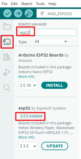
- To use ESP32-based boards in the Arduino IDE, you must first install the “esp32 by Espressif Systems” board package.
- Install in accordance with the panel installation requirements
Once you have opened the software
File - Preferences
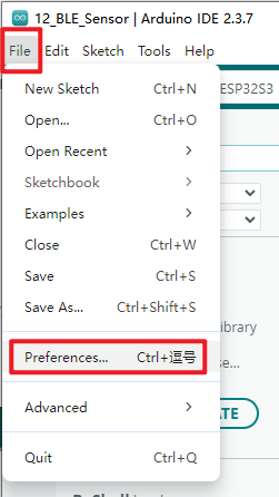
Add the address of the development board manager
-
Link to the stable release:
https://espressif.github.io/arduino-esp32/package_esp32_index.json
-
Link to the development version:
https://espressif.github.io/arduino-esp32/package_esp32_dev_index.json
 When you have finished, select OK
- Select the Development Board Manager on the left-hand side of the software
- Search for 'esp32' in the search bar
- In the version field for the ‘esp32 by Espressif Systems’ development board found in the search results, select a version of 3.2.0 or higher
- Click to install
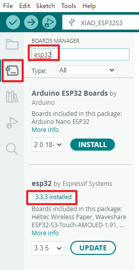
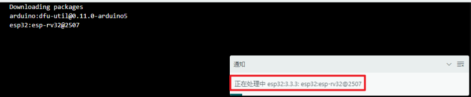
- Once you click it, a message like this will appear in the bottom-right corner of the software; please wait for the download to complete (ensure you have a stable internet connection whilst waiting).
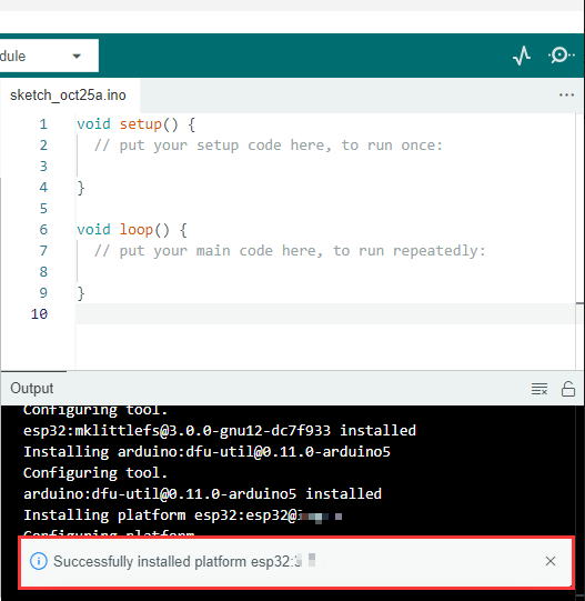
- Once the download is complete, a success message will appear
- When you search again, the word ‘installed’ will appear
Development Board Type Configuration
The development board is an ESP32S3 Dev Module
Before each burn, you must check that the development board type is correct.
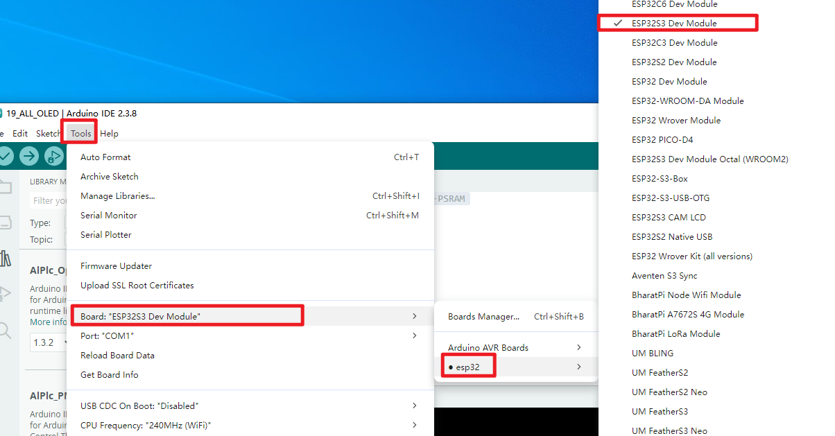
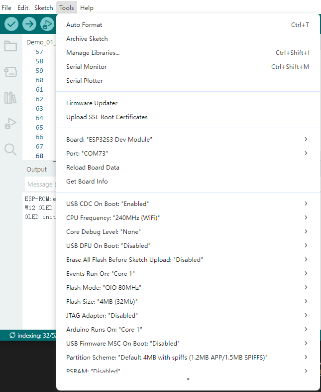
ESP32S3 Dev Module Version and Parameter Configuration
Install the required libraries
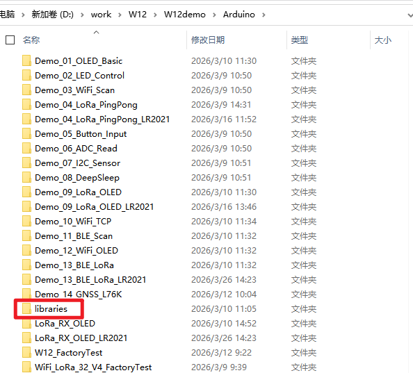
When installing Arduino libraries, there are usually two options available: online installation and offline installation. If a library requires offline installation, you must use the provided library files. For most libraries, users can easily search for and install them via the Arduino software’s online library manager. However, some open-source or custom libraries are not synchronised with the Arduino library manager and therefore cannot be obtained via an online search. In such cases, users must install these libraries manually using the offline method.
As the library files for this product are already included in the compressed package for the sample programme, there is no need to download any additional libraries.
Sample programme
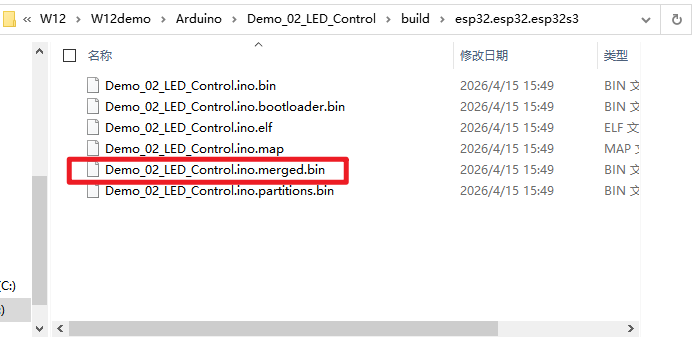
All example programmes have their own .ino files, which you can modify based on the source code to achieve the desired results. There are also pre-compiled .bin files that can be flashed directly using the flash_download_tool.
The bin files ending in ‘merged’ within the ‘build’ folder of each demo can be flashed directly.
Firmware flashing
flash_download_tool
Download the flash_download_tool Official download link:https://dl.espressif.com/public/flash_download_tool.zip
Introduction to the Tool
Interface entry point
Open the Flash download tool; double-click the .exe file to access the main interface, as shown below:

-
ChipType:Chip type: select according to the type of product used -
WorkMode:Software modes: there are currently two modes—Develop mode and Factory mode—with the differences outlined below:-
DevelopThis mode uses the absolute path of the firmware and only supports flashing for single-chip products. -
FactoryAs the mode uses relative paths, we recommend placing the firmware to be flashed in a ‘bin’ folder at the same level as the .exe file; the configuration will be automatically saved locally when you close the application. -
FactoryWhen opened, the interface is locked; you must click the ‘Lock Settings’ button to enable editing. This prevents accidental mouse operations.
-
-
LoadMode:The download interface supportsUARTandUSB
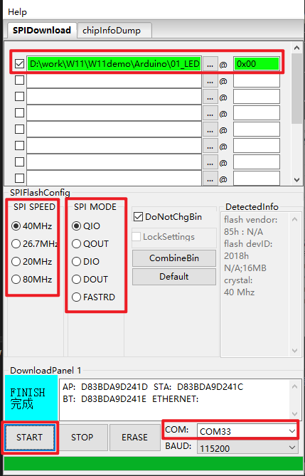
SPIDownload interface
The following are the configuration instructions:
-
Download Path ConfigInclude the firmware load path and firmware download address, entered in hexadecimal format, for example 0x1000。 -
SPI Flash Config-
SPI SPEED:SPI start rate -
SPI MODE:SPI boot mode -
DETECTED INFO:Automatically detected flash and crystal oscillator information -
DoNotChgBin:If enabled, the original contents of the bin file will be flashed. If disabled, the settings will be updated and flashed according to the SPI SPEED and SPI MODE configurations on the interface. -
CombineBinbutton:You can bundle multiple firmware files selected in the Download Path Config into a single firmware file. If DoNotChgBin is enabled, the files will be bundled as-is. If DoNotChgBin is not enabled, the firmware will be bundled according to the SPI SPEED and SPI MODE settings on the interface. Non-data areas between firmware files will be filled with 0xff. The combined firmware will be saved as ./combine/target.bin; each time you click, the previous version will be overwritten. -
Defaultbutton:Reset all SPI interface settings to their default values
-
-
Download Panel-
START:Start button -
STOP:Stop button -
ERASE:Complete flash erase -
COM:Download Serial Port -
BAUD:Download baud rate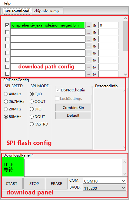
-
FactoryMultiDownload Interface
-
FactoryThe mode uses relative paths, loading the firmware to be flashed from thebindirectory within the tool directory by default. TheDevelopmode, however, uses absolute paths. The advantage of theFactorymode is that once the firmware to be flashed has been copied to thebindirectory within the tool directory, it can be copied between factory computers without encountering any path issues. -
When the
Factorymode is enabled, the tool launches withLockSettingsenabled by default. WhenLockSettingsis enabled, neither the firmware path nor theSPI flash configcan be configured, thereby preventing configuration errors caused by accidental changes made by production line staff. (Factory managers who need to make configurations can clickLockSettingsto unlock it.)
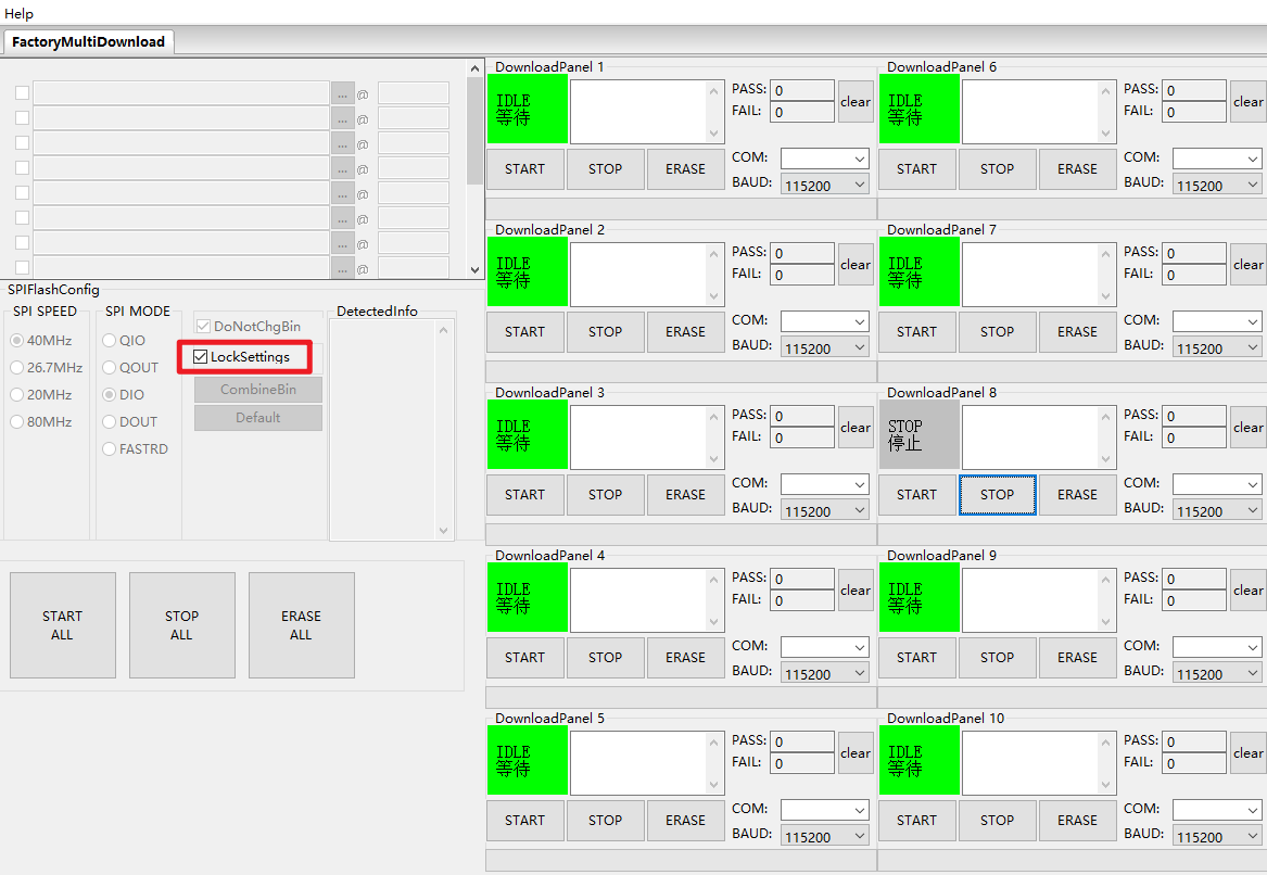
The download path config and SPI flash config settings on the FactoryMultiDownload interface are essentially the same as those on the SPIDownload interface. Please refer to [[#SPIDownload interface]] and ensure that you configure the serial port number and baud rate for each channel individually.
chipInfoDump Interface
-
DeviceSelect the serial port number and baud rate for the relevant device. -
Read Flash: Select the starting address and the size of the data to be read from the flash memory. This option only needs to be set when reading from the flash memory.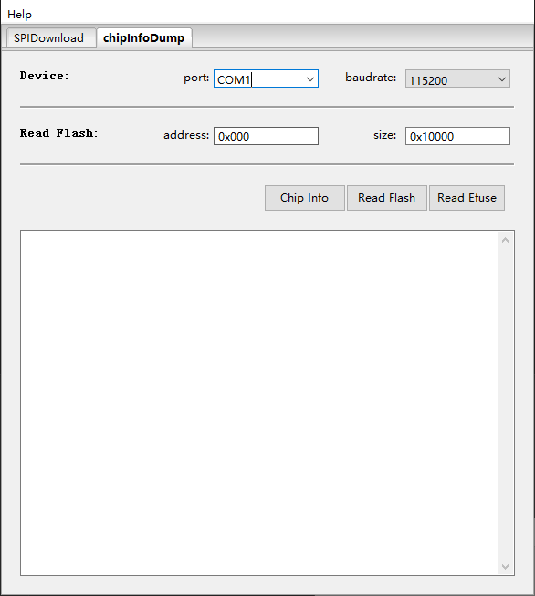
-
Function Description
-
Chip Info:Read the chip model, flash ID and flash status register values; the data is displayed directly on the software interface. -
Read Flash:Read data from the flash memory. The read data is stored in the generated bin file, which is named in the format: “chip MAC + start address of the read data + length of the read data + time of the read”. -
Read Efuse:Reads the contents of the chip’s eFuse; this function is identical to the esptool summary command. The read data is stored in a generated text file, which is named in the format “chip MAC + read time”.
-
Download examples
This section uses the ESP32-S3 series as an example to demonstrate how to perform standard and encrypted flashing.
Standard programming
-
Pull the GPIO0 pin low to put the device into download mode.
-
Open the download tool, select
ESP32forChipType,DevelopforWorkMode, andUARTforLoadMode, then clickOK, as shown in the figure below.
-
Go to the download page, enter the bin file you wish to flash and the corresponding flash address, tick the checkbox next to the bin file, and enter the values for
SPI SPEED,SPI MODE,COMandBAUDaccording to your specific requirements. -
Click
STARTto begin the download. During the download, the download tool will read the flash memory information and the chip’s MAC address. -
Once the download is complete, the download tool’s interface will appear as shown below.
Demo_01_OLED_Basic
Programme Description
This demonstration programme is designed to verify the basic functions of the OLED on the W12. Upon power-up, the programme enables Vext, initialises the OLED, and then loops through the following:
-
- Text display demonstration
-
- Basic graphics demonstration (rectangles, circles, straight lines, progress bars)
-
- Simple animation demonstration (moving squares + breathing circles) Hardware:
- Development board: ESP32-S3 development module (W12)
- OLED: I2C, SDA=GPIO17, SCL=GPIO18, RST=GPIO47
- Vext power control: GPIO45
- As the current OLED screen’s driver chip is the SSD1315, and the SSD1315 is an upgraded version of the SSD1306 that is compatible with all SSD1306 commands, the current programme uses the
HT_SSD1306Wire.hdriver
Hardware connections
- Connect the board to the computer using a USB cable
Performance
- The OLED screen will display text, basic shapes (rectangles, circles, straight lines, progress bars) and animations (moving squares, breathing circles) in sequence.
Demo_02_LED_Control
Programme Description
Using the Adafruit_NeoPixel library to drive an RGB LED connected to GPIO46, enabling basic colour cycling, rapid flashing, smooth colour transitions and a breathing light effect.
Key features include:
-
Initialise the single on-board RGB LED using the RGB colour format and a communication rate of 800 kHz
-
Implement a cyclical display of the three primary colours—red, green and blue, switching automatically every 500 ms
-
Offers a rapid six-colour flashing effect, alternating between red, green, blue, yellow, cyan and purple
-
Supports a smooth brightness gradient in warm yellow, with brightness gradually increasing from 0 to 255 and then gradually decreasing back to 0
-
Create a blue-green breathing light effect, with the light flickering on and off in a slow, rhythmic pattern
-
All lighting effects are displayed in an automatic loop, with the current display status output via the serial port
-
Provides a standard
setColor()function, making it easy to customise any RGB colour
Hardware connections
- Connect the board to the computer using a USB cable
Performance
- The LED lights built into the product board cycle through four different lighting effects
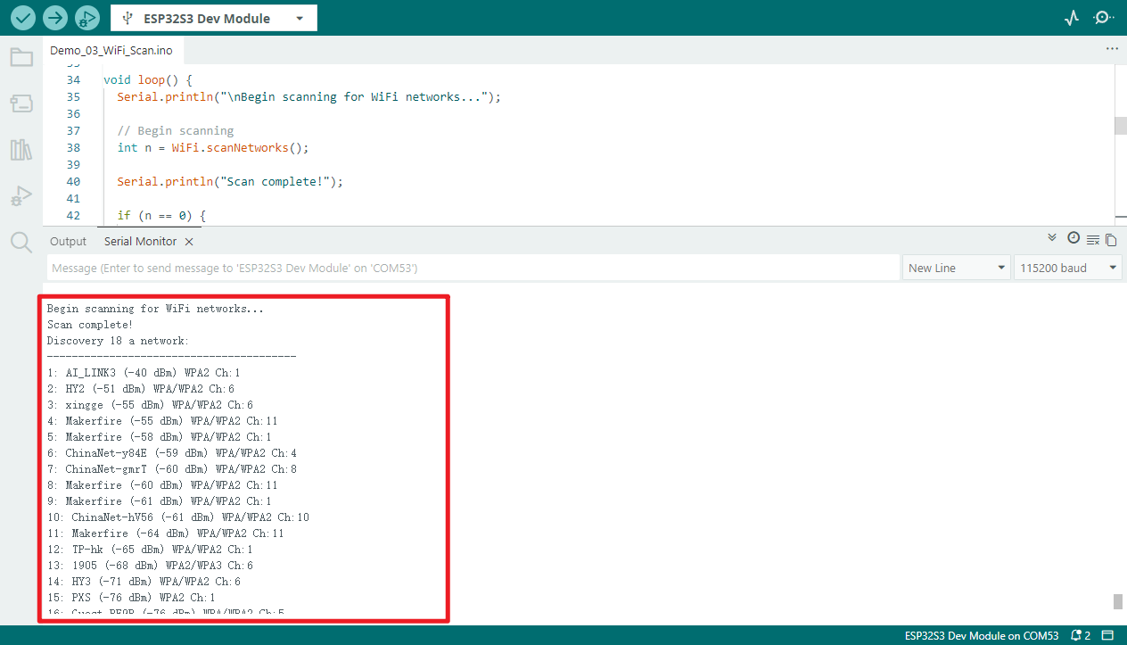
Demo_03_WiFi_Scan
Programme Description
This programme is designed to demonstrate the W12’s Wi-Fi scanning functionality. Upon launch, it sets the Wi-Fi to STA mode and periodically scans for nearby 2.4GHz Wi-Fi networks. After each scan is complete, a list of networks is output via the serial port, including:
-
SSID (network name)
-
RSSI (Received Signal Strength Indicator)
-
Encryption type
-
Channel number
The programme automatically repeats the scan every 5 seconds, allowing you to monitor changes in the surrounding Wi-Fi environment in real time.
Hardware connections
- Connect the board to the computer using a USB cable
Performance
- Open the serial monitor at a baud rate of
115200 - View all Wi-Fi information detected by the device
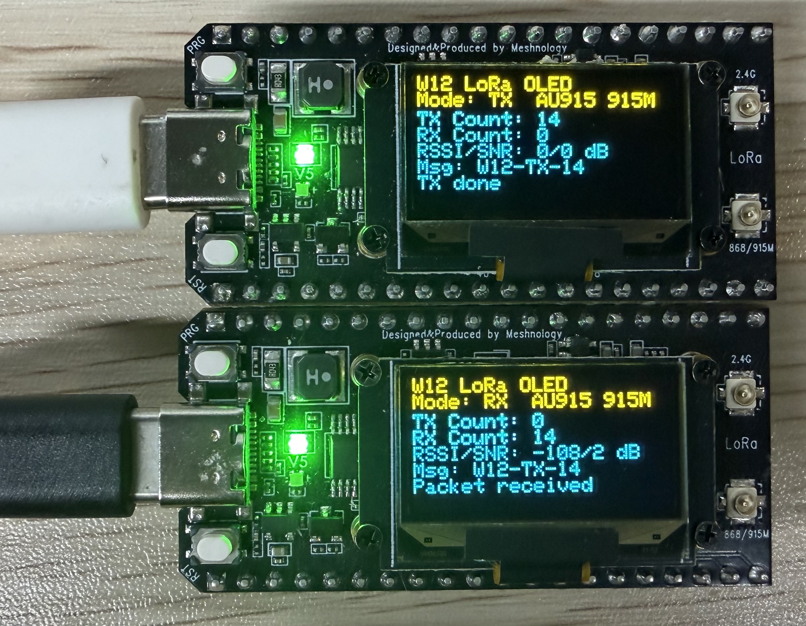
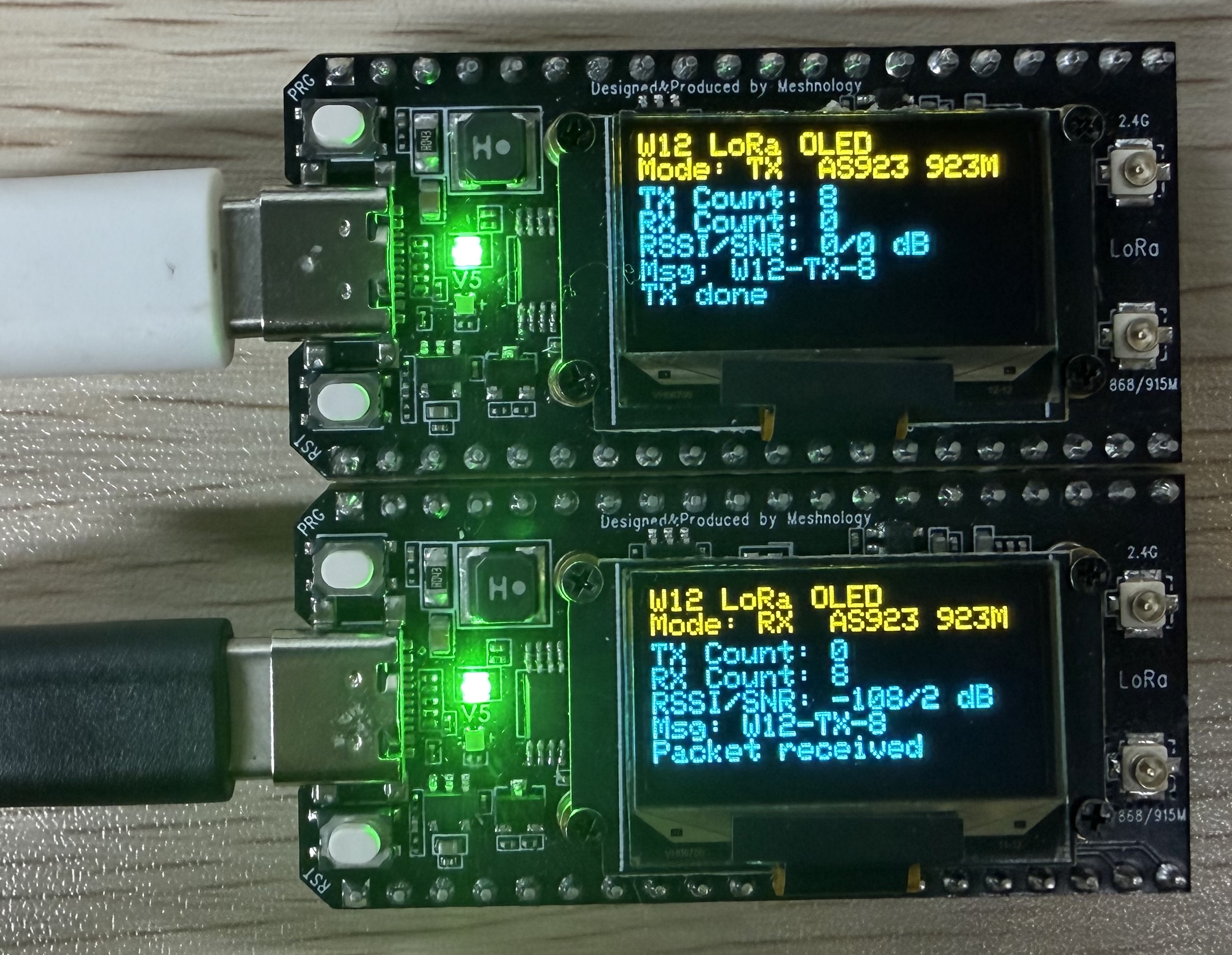
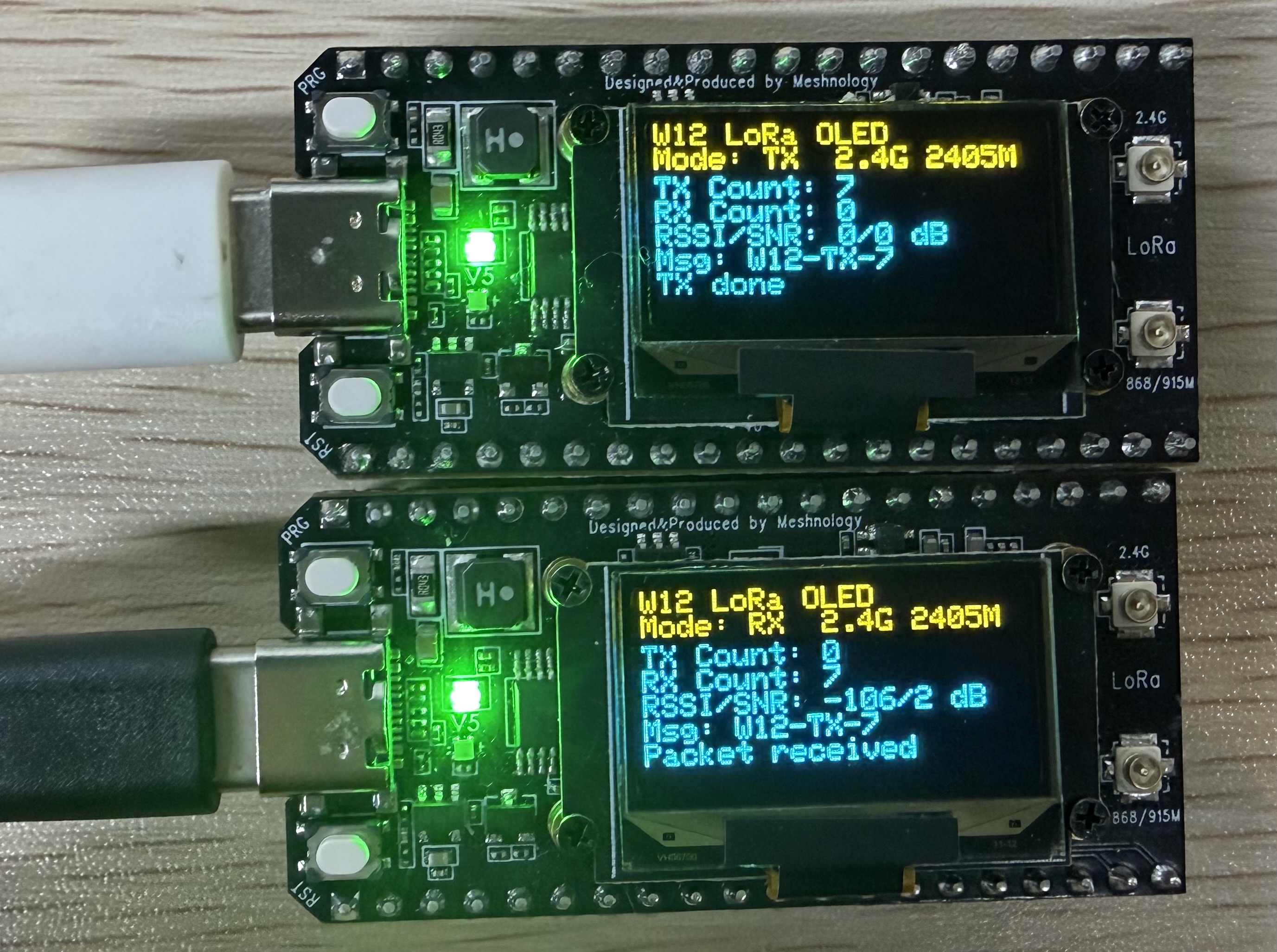
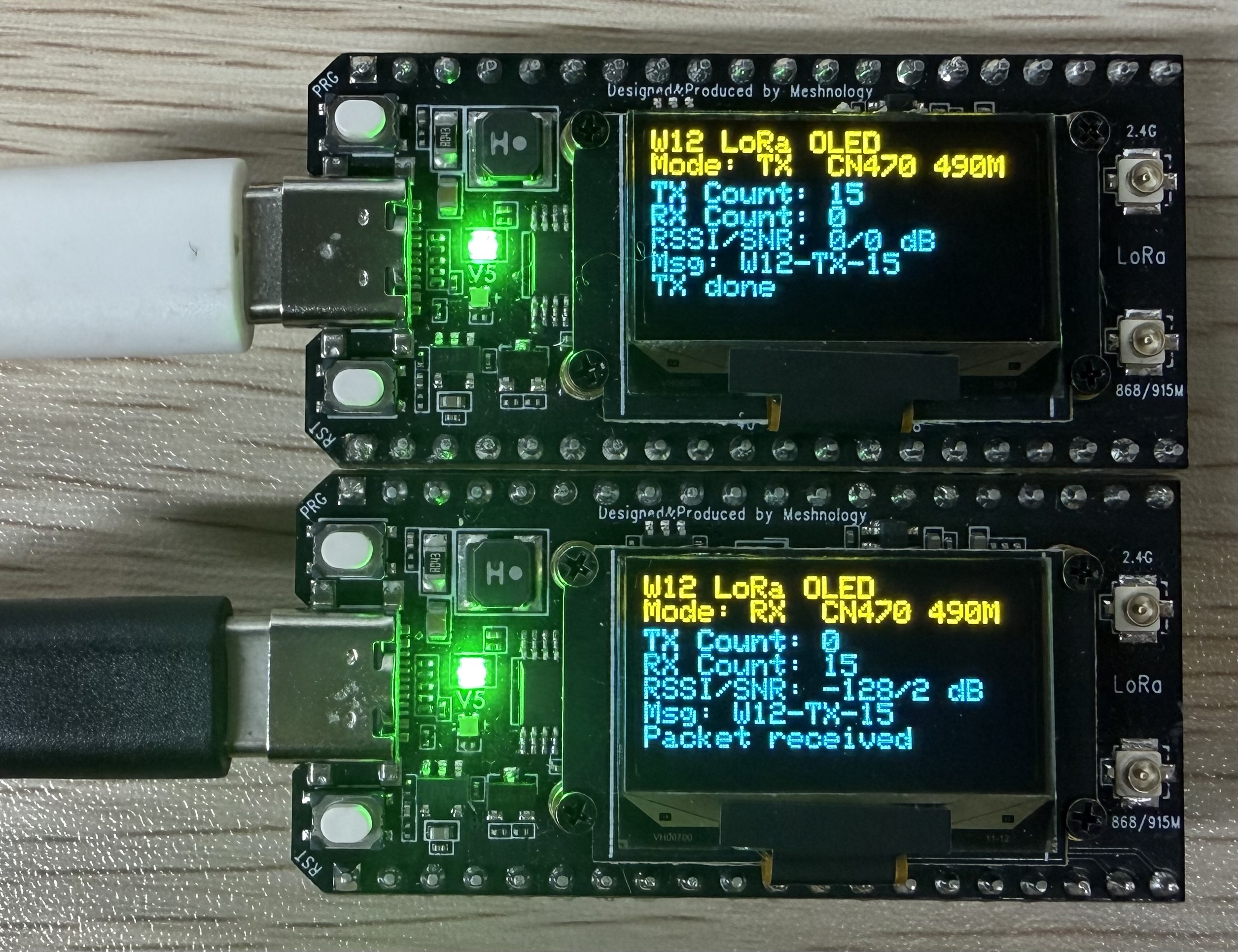
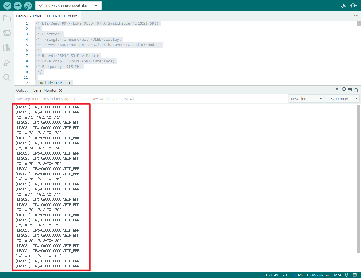
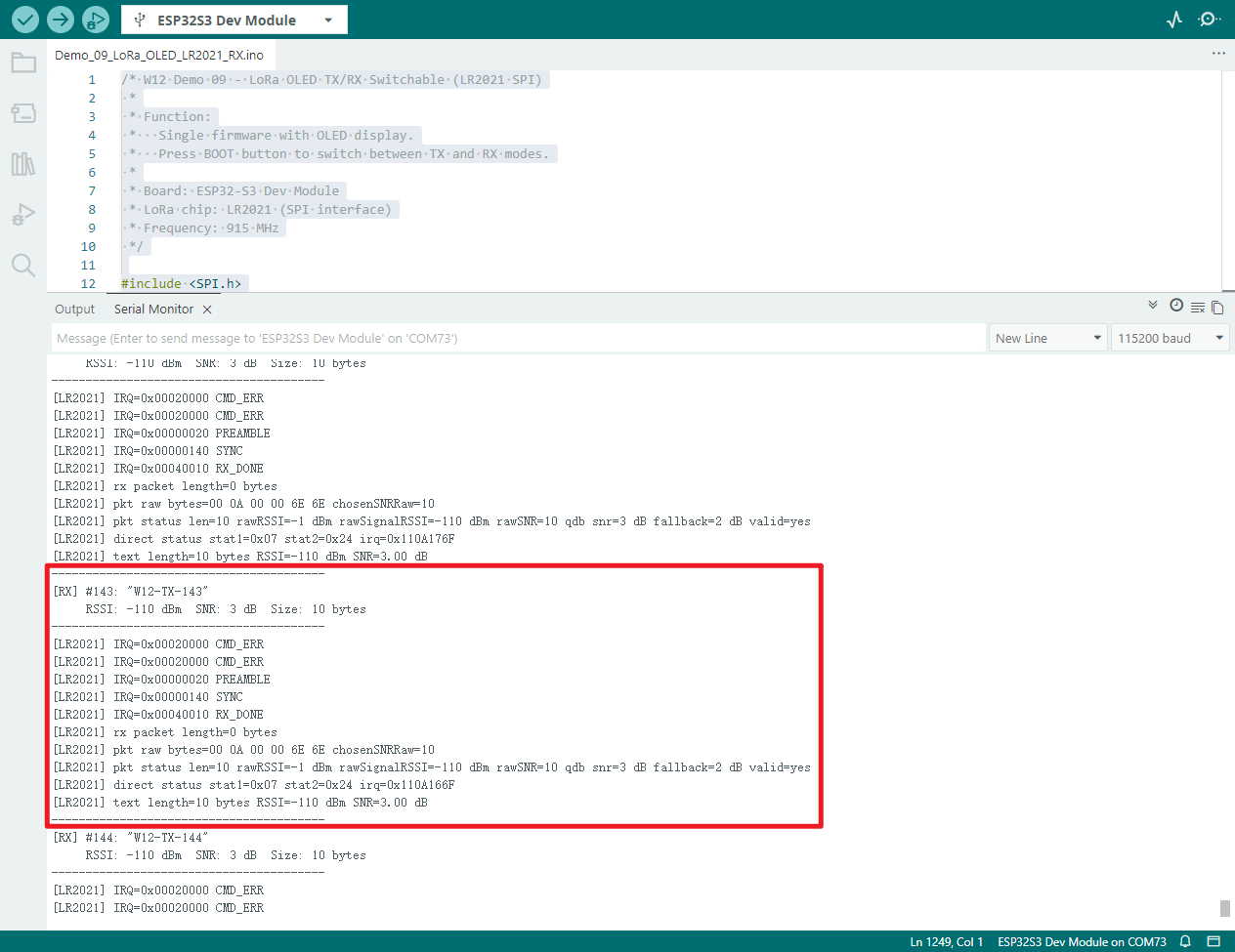
Demo_04_LoRa_OLED_LR2021
Programme Description
This demonstrates the LoRa wireless transceiver functionality of the W12 development board, which supports one-touch switching between transmit and receive modes, allows for flexible frequency switching, and features an OLED display showing real-time status and data. It can operate independently without the need to connect to a computer.
Key features include:
-
Upon startup, the device defaults to LoRa receive mode, continuously monitoring wireless data in the air
-
Press the BOOT button briefly to cycle through the different frequency bands (CN470/US915/EU868, etc.)
-
Press and hold the BOOT button to switch between receive (RX) and transmit (TX) modes
-
In TX mode, a data packet containing the transmission sequence number is automatically sent every second
-
In RX mode, packets are automatically parsed upon reception, displaying signal strength (RSSI) and signal-to-noise ratio (SNR)
-
The OLED screen displays the following in real time: operating mode, band, transmit/receive count, signal strength and latest messages
-
Serial port synchronous output of transmission and reception logs, data content, and RSSI/SNR parameters for easy debugging
-
Automatically switch on the VEXT power supply to power the OLED, completing screen initialisation and status refresh
-
Pre-configured with standard LoRa parameters to ensure reliable communication with other LoRa devices
Hardware connections
- Connect the board to the computer using a USB cable
Performance
Actual appearance
US915 Frequency band
EU868 Frequency band
KR920 Frequency band
NZ915 Frequency band
AU915 Frequency band
AS923 Frequency band
2.4G Frequency band
CN470 Frequency band
TX serial port output data
RX serial output data
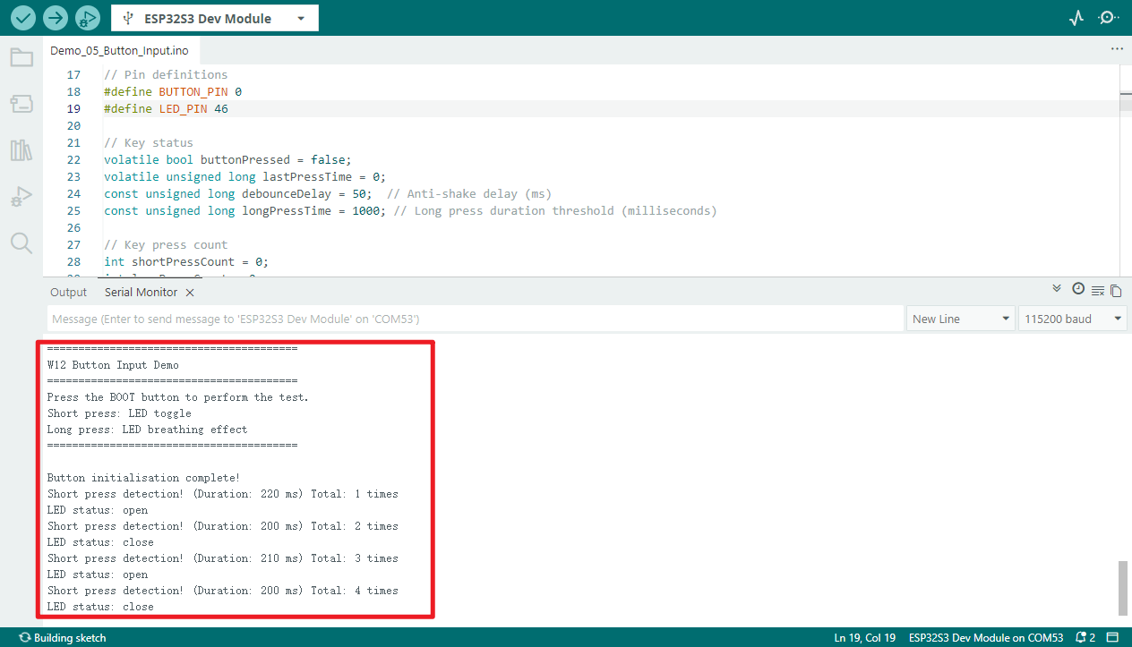
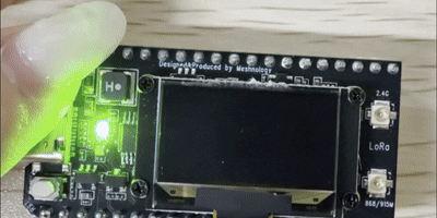
Demo_05_Button_Input
Programme Description
The on-board BOOT button (GPIO0) is used to detect short and long presses, with RGB LEDs providing visual feedback; the system also includes button debouncing and secure interrupt handling.
Key features include:
-
Using an interrupt-based approach to detect key presses ensures a fast response time and does not consume main loop resources
-
Built-in 50 ms button debouncing effectively prevents false triggers caused by voltage fluctuations
-
Automatically detects two operating modes: short press less than 1000 ms and long press greater than or equal to 1000 ms
-
When the button is pressed briefly, the RGB LED cycles through eight colours (red, green, blue, yellow, cyan, magenta, white and off).
-
When the button is held down, the RGB LED automatically cycles through a cyan-blue breathing light effect
-
Real-time serial output of key type, press duration, cumulative count and current LED colour
-
The button uses an internal pull-up configuration, requiring no external circuitry; simply use the on-board BOOT button.
-
Interrupt service routines (ISRs) are modified using IRAM ATTR to ensure operational stability
Hardware connections
- Connect the board to the computer using a USB cable
Performance
-
Open the serial monitor
-
Press the boot button to turn the LED on or off
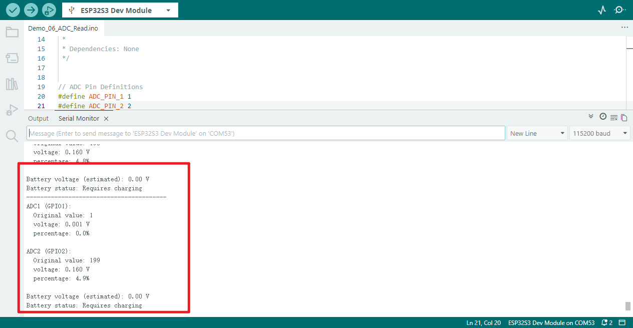
Demo_06_ADC_Read
Programme Description
This programme demonstrates the ADC analogue acquisition capabilities of the W12. It periodically reads from two ADC channels (GPIO1 and GPIO2), reduces noise by averaging multiple samples, and outputs the results to the serial port after converting them to voltage values and percentages.
Key features include:
-
Configure 12-bit ADC resolution with 11 dB attenuation (approximately 0–3.3 V range)
-
Dual-channel sampling and averaging filter
-
Raw values, voltage values, percentage display
-
Estimates the battery voltage based on the voltage divider assumption and outputs the state of charge (fully charged/good/low/needs charging)
Hardware connections
- Connect the board to the computer using a USB cable
Performance
-
Dual-channel ADC sampling (10-point averaging)
-
Raw values, voltage, percentage display
-
Battery Voltage Estimation and Condition Assessment
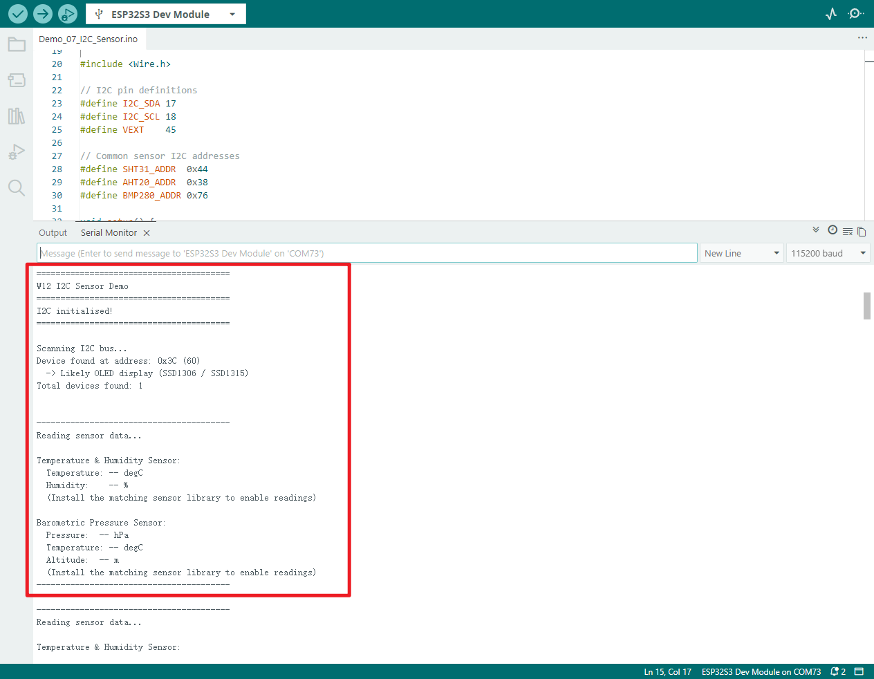
Demo_07_I2C_Sensor
Programme Description
By powering up external sensors, initialising the I2C bus, scanning all devices on the bus, and providing a framework for reading data from common sensors such as temperature, humidity and barometric pressure, this system enables the rapid identification and integration of various I2C sensors.
Key features include:
-
Control the VEXT power supply to power external I²C sensors, ensuring the hardware functions correctly
-
Initialise the I2C bus (SDA:17 / SCL:18), supporting the standard 100 kHz communication rate
-
Automatically scans all slave addresses on the I2C bus and identifies common devices (OLED, AHT20, SHT31, BMP280, etc.)
-
Provides a framework for reading data from temperature, humidity and barometric pressure sensors, facilitating integration with real-world sensor libraries
-
Encapsulates utility functions for reading and writing generic I2C registers, which can be used directly in various I2C device drivers
-
Periodic output of sensor data alerts; supports polling at 2-second intervals
Hardware connections
-
Connect the board to the computer using a USB cable
-
If you need to add a sensor, you can use this programme to check whether it is connected correctly.
Performance
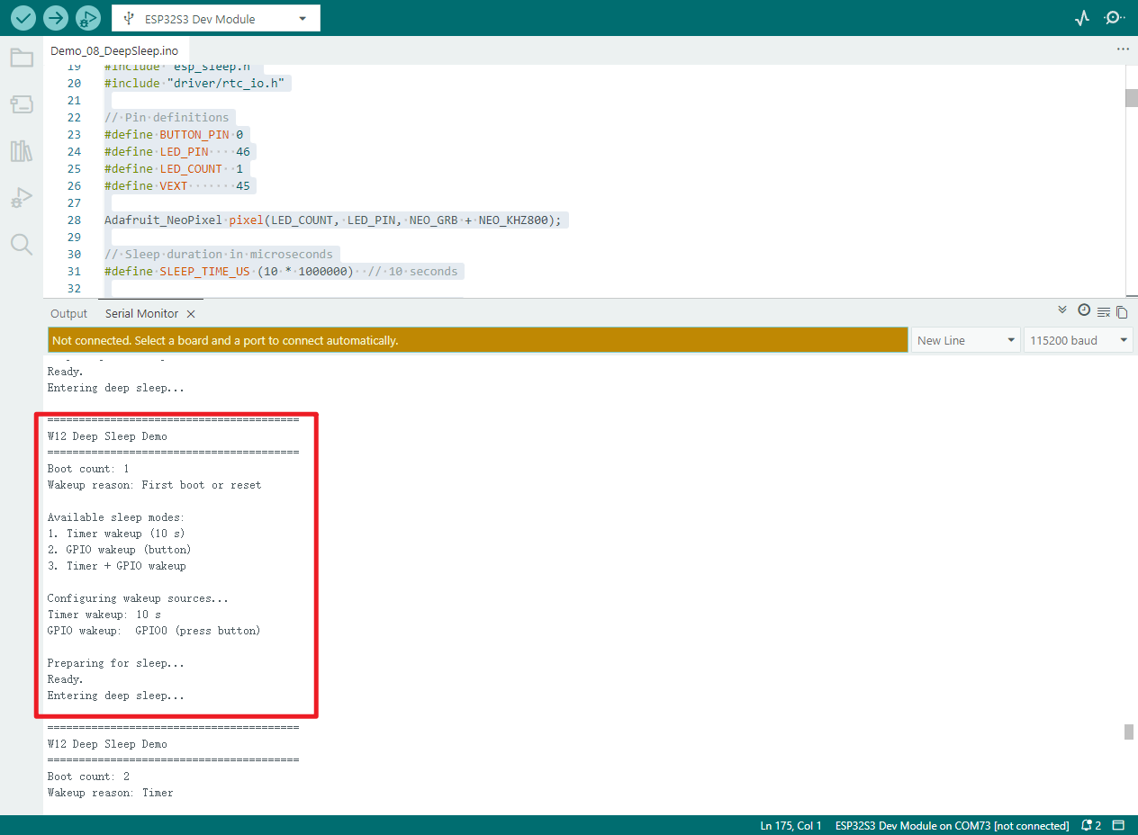
Demo_08_DeepSleep
Programme Description
The programme implements timer wake-up, GPIO button wake-up and a combination of both wake-up sources. Upon waking, it provides a visual indication via an RGB LED whilst simultaneously switching off the external power supply to minimise power consumption.
Key features include:
-
Use RTC to store variables that record the number of times the system has been booted; the data remains unchanged during deep sleep
-
Automatically detects and prints the reason for wake-up (timer, GPIO button, first boot or reset)
-
Supports a 10-second automatic wake-up timer
-
Supports manual wake-up via GPIO0 (BOOT button)
-
Uses a dual wake-up source mode combining a timer and a button; the device will wake up when either condition is met
-
Upon waking, the RGB LED flashes blue three times as an indicator
-
Switch off the RGB LEDs and the external VEXT power supply before entering sleep mode to optimise power efficiency
-
Outputs complete sleep status, wake-up information and statistics via the serial port
-
After deep sleep, the programme restarts from
setup(); theloop()function is never executed
Hardware connections
- Connect the board to the computer using a USB cable
Performance
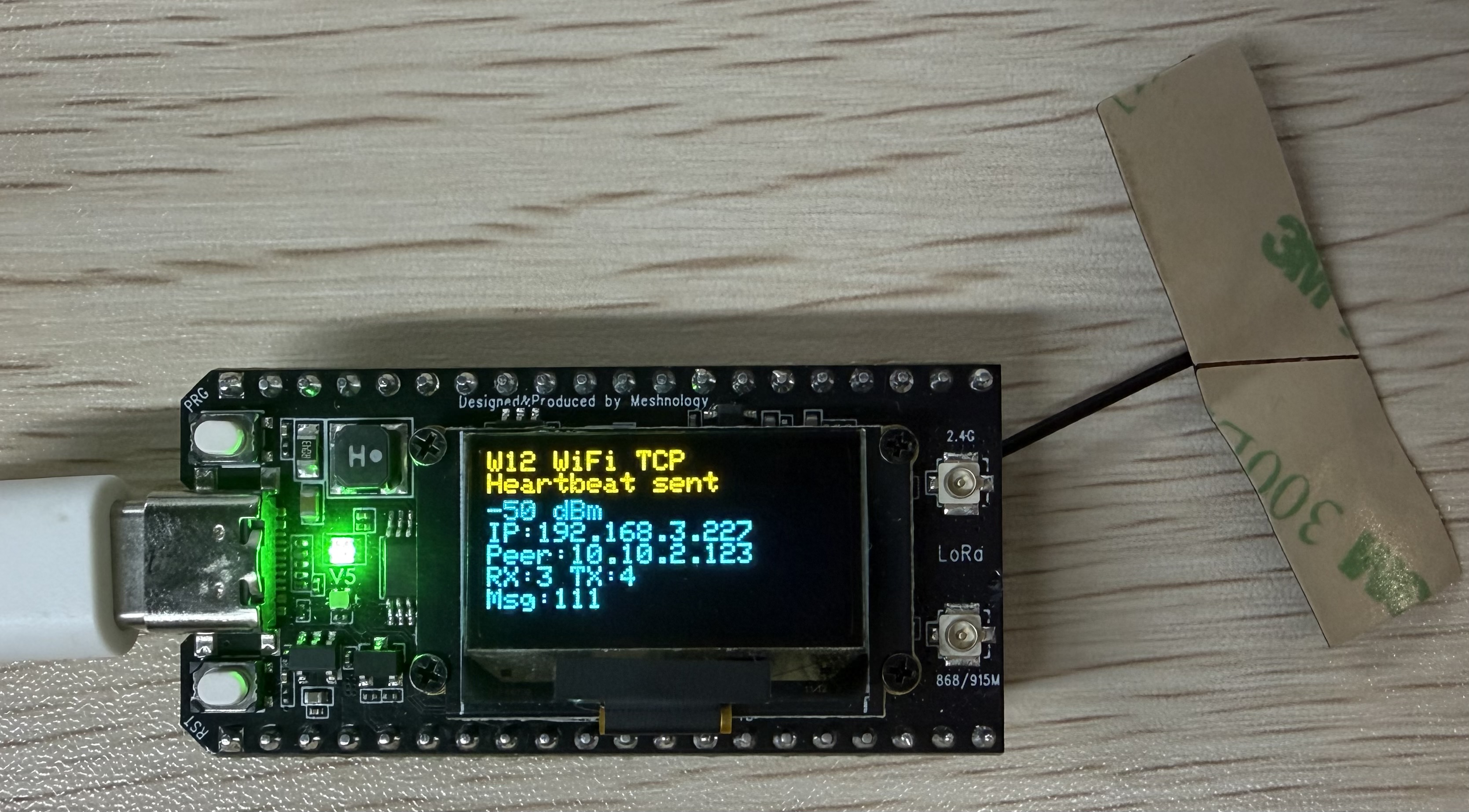
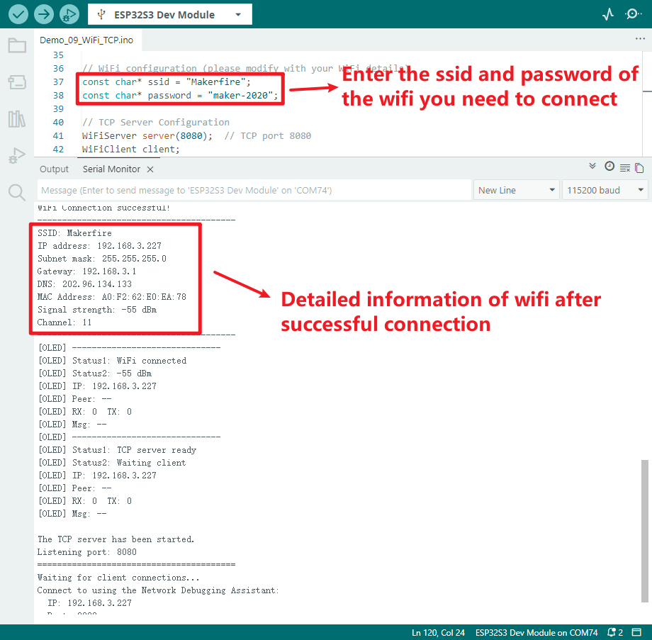
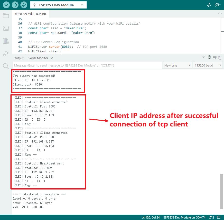
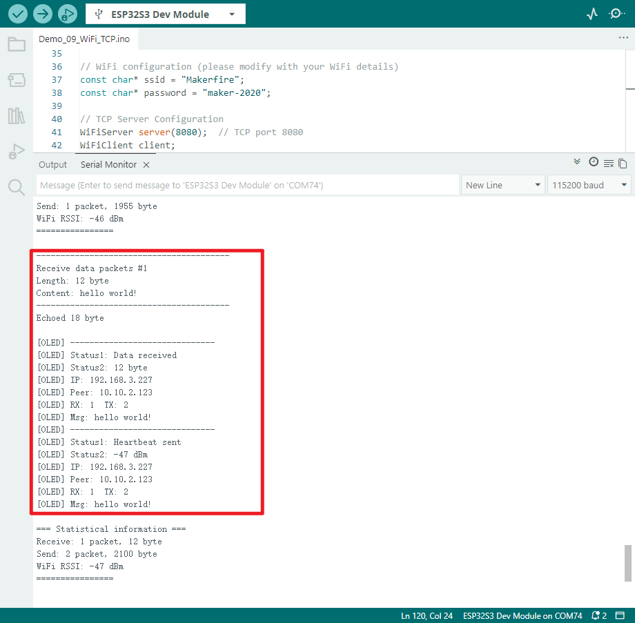
Demo_09_WiFi_TCP
Programme Description
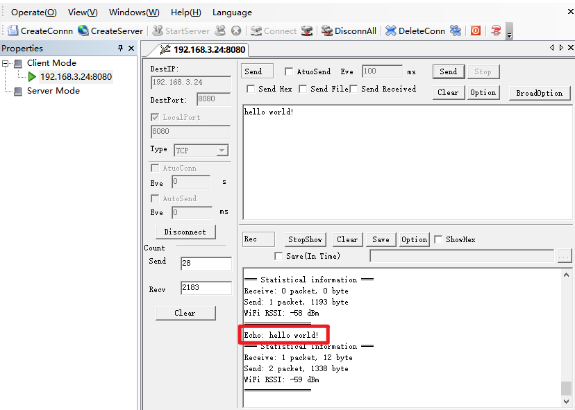
This programme demonstrates the 2.4GHz Wi-Fi TCP server’s data transmission and reception capabilities on the W12 development board. Once connected to a router, the device establishes a TCP server and waits for clients—such as the Network Debugging Assistant—to connect, enabling bidirectional data passthrough, echo testing and status monitoring.
Key features include:
-
Connect to a specified 2.4GHz Wi-Fi network in STA mode, automatically obtain an IP address, and support automatic reconnection
-
Set up a TCP server on port 8080 to await remote connections from clients
-
Supports single-client connections; a welcome message is sent automatically upon connection
-
Receive client data and echo it back unchanged, to perform a bidirectional pass-through test
-
Automatically sends a statistical heartbeat packet to the client every 10 seconds, containing send/receive counts and Wi-Fi signal strength
-
The OLED screen displays the following in real time: Wi-Fi status, local IP address, client IP address, number of packets sent and received, and latest messages
-
Complete serial port output of connection information, transmitted and received data, signal strength and network parameters
-
Automatically power on the VEXT to supply power to the OLED, thereby completing screen initialisation and real-time refresh
-
Automatically restore the server’s state in the event of a connection failure, maintaining continuous monitoring
Hardware connections
-
Connect the board to the computer using a USB cable
-
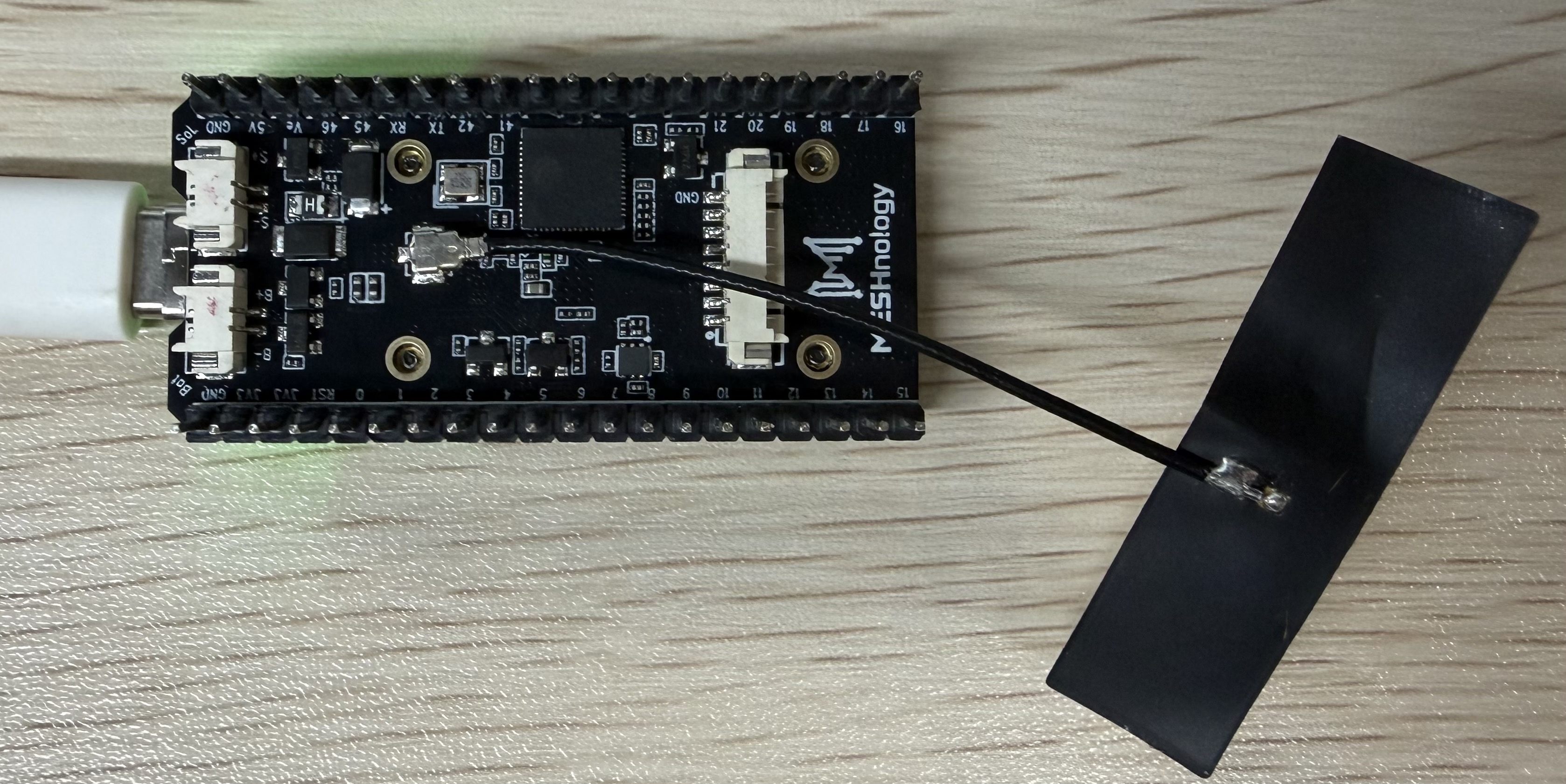
If you are unable to connect to Wi-Fi, you can attach a Wi-Fi antenna to the back of the board
Performance
Once the programme is running, you can view the IP address assigned upon connecting to Wi-Fi, the IP address of the TCP client, and the data received on the screen.
-
Real-time output of connection status, received data content and transmitted data length
-
Display WiFi connection details and statistics
-
to facilitate debugging and monitoring the programme’s running status
Use a TCP connection tool to establish a connection and send a message, and check whether data can be transmitted successfully
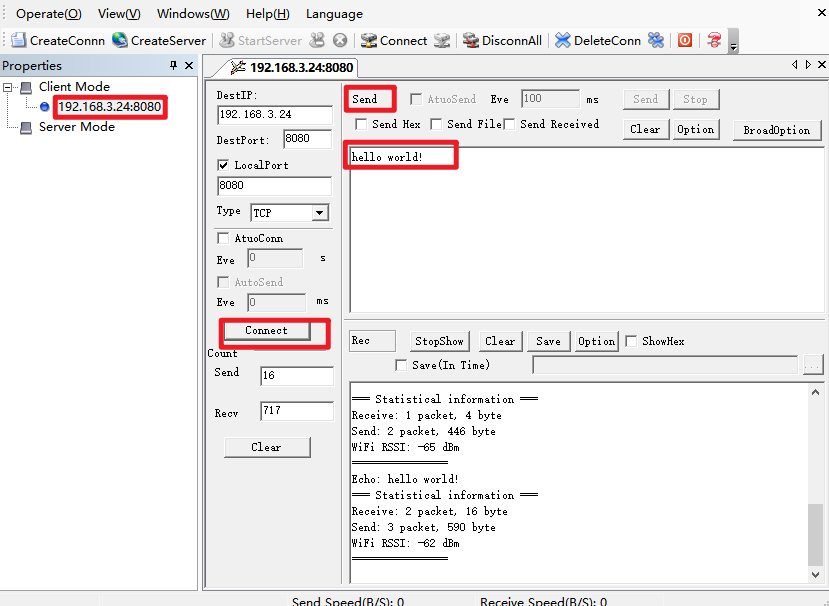
Once the connection is established, the device’s serial port will display a message indicating that the client has connected.
Sent successfully
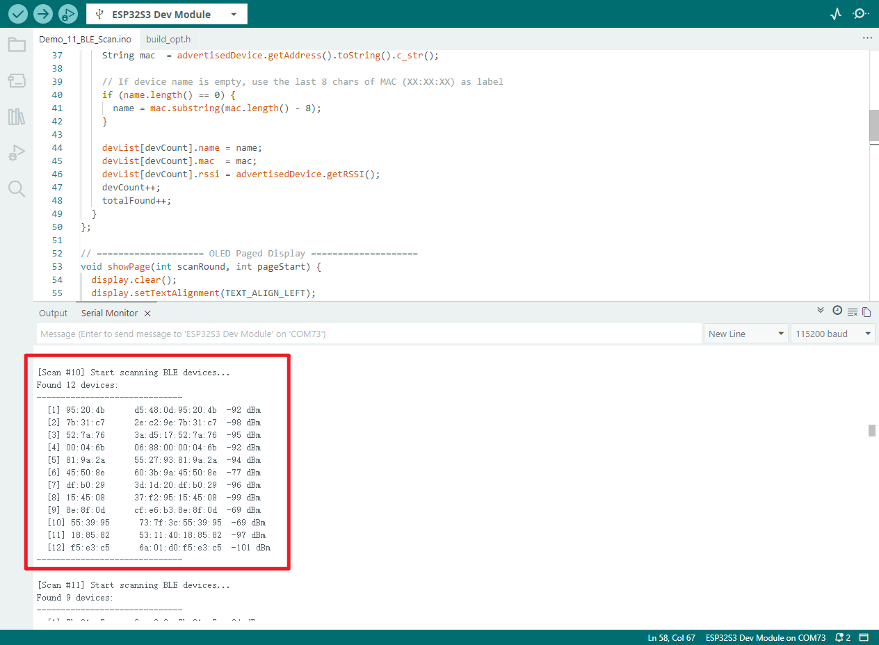
Demo_10_BLE_Scan
Programme Description
This programme demonstrates the BLE Bluetooth scanning functionality of the W12 development board. It automatically searches for nearby Bluetooth devices and displays the device name, MAC address and signal strength (RSSI) in real time on the OLED screen. It operates independently without the need for pairing with a mobile phone.
Key features include:
-
Initialise the BLE device and enable active scanning mode; set the duration of each scan cycle to 3 seconds
-
Automatically detects and records nearby BLE devices, caching information for up to 20 devices
-
For unnamed Bluetooth devices, the last 8 digits of the MAC address are automatically used as the device identifier
-
The scan results are displayed in pages on the OLED screen (four devices per page), with automatic page scrolling
-
Displays the scan cycle, number of devices detected, current page number, device name and RSSI signal strength in real time
-
Complete scan list (serial number, name, MAC, RSSI) output via serial port for convenient debugging and viewing
-
Automatically switch on the VEXT power supply to power the OLED, completing screen initialisation and status refresh
-
A 'Please wait' message appears on the screen during scanning, enhancing the user experience
-
Once the scan is complete, the results are automatically cleared and the next cycle begins.
Hardware connections
- Connect the board to the computer using a USB cable
Performance
-
After power-up, the OLED display initialises and then begins a BLE scan.
-
During scanning, the screen displays ‘Scanning’; a full scan cycle takes 3 seconds.
-
The scan results are displayed in a paginated scroll view on the OLED screen, with four devices per page.
-
Displays the device name and signal strength; for unidentified devices, the MAC address is displayed.
-
If no device is present, the screen displays a message stating that no BLE device has been found.
-
Device information is output to the serial port, and scanning automatically restarts once a cycle is complete.
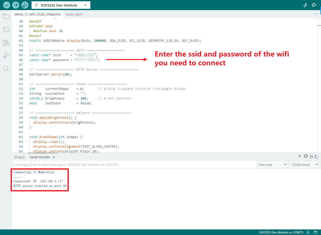
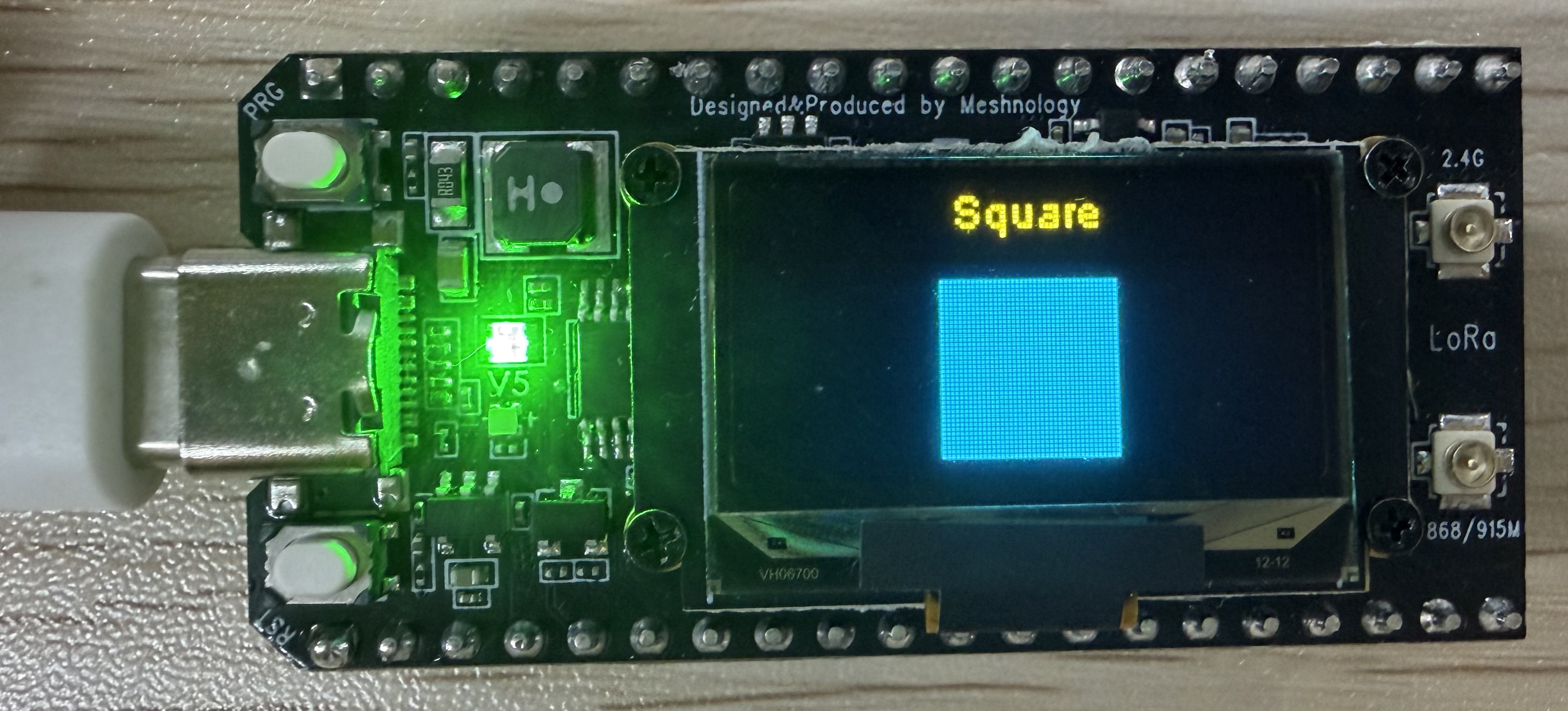
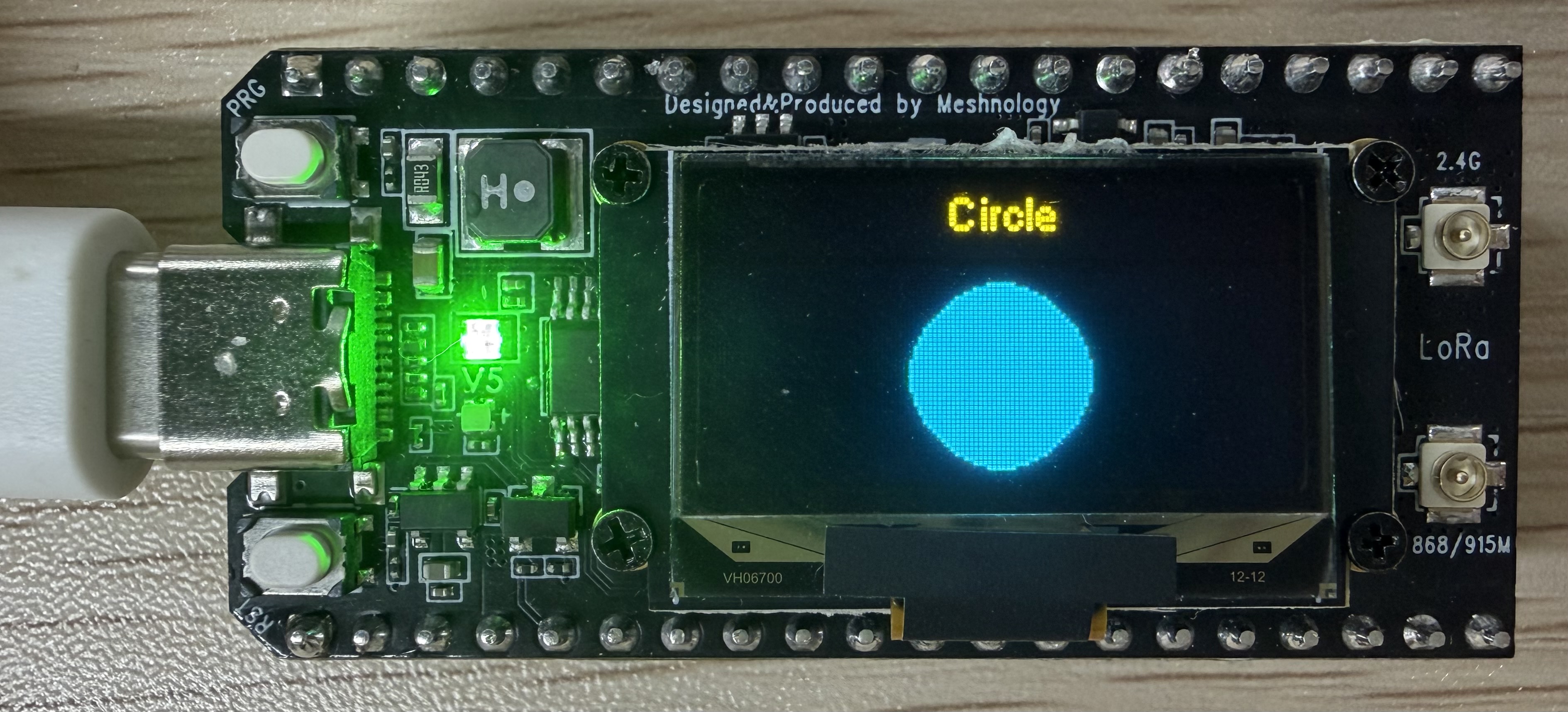
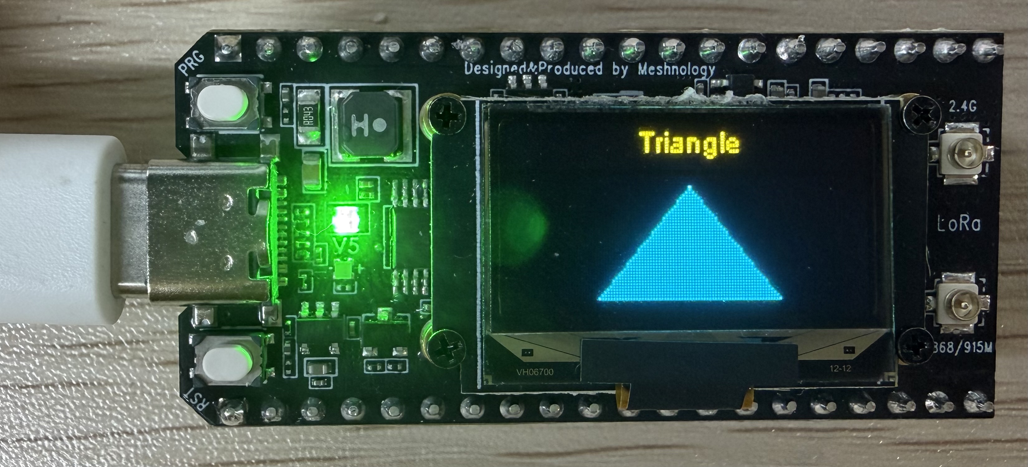
Demo_11_WiFi_OLED_Shape
Programme Description
This programme demonstrates the WiFi web-based remote control functionality of the W12 development board. Once the device is connected to a WiFi network, it launches a web server; users can then access the device’s IP address via a web browser to remotely control the OLED display, adjust the brightness, switch the RGB LEDs on and off, and view the device’s operational status in real time.
主要功能包括:
-
Connect to the specified Wi-Fi network, start a web server on port 80, and display the access IP on the OLED screen
-
The web interface provides a graphical control panel that supports remote switching between three display shapes: square, circle and triangle.
-
Supports entering custom text via a web page and displaying it in real time in the centre of the OLED screen
-
Features a brightness slider that allows you to adjust the OLED contrast (10–255) with the changes taking effect immediately
-
Supports remote control of the on-board green RGB LED and displays the switch status synchronously on the web page
-
Provides a screen-clear button to clear the OLED display and return to the standby screen with a single tap
-
The web page displays WiFi signal strength (RSSI), device uptime, current display mode and LED status in real time
-
Built-in automatic reconnection mechanism in the event of a WiFi disconnection, ensuring stable and uninterrupted remote control
-
Automatically switch on the VEXT power supply to power the OLED, thereby completing screen initialisation and display refresh
-
The website features a green tech design and is optimised for viewing on a range of devices, including computers and mobile phones.
Hardware connections
-
Connect the board to the computer using a USB cable
-
If you have checked that the SSID and password are correct but are still unable to connect via Wi-Fi, you will need to attach an antenna to the Wi-Fi antenna connector on the back of the board.
Performance
Once you have entered the SSID and password, the device will display the IP address once the Wi-Fi connection is successful. You can then access the corresponding web address using a web browser.
Once the request is successful, the corresponding control buttons and other elements will appear on the webpage
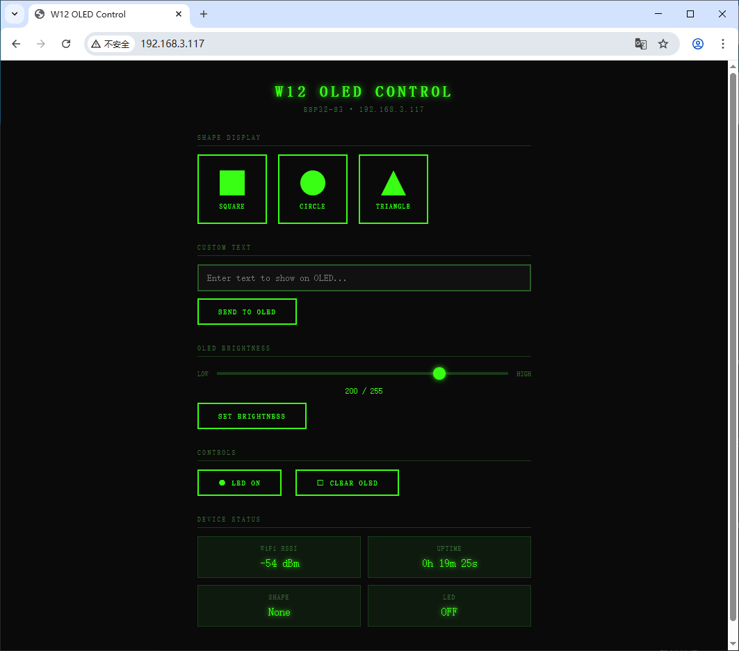
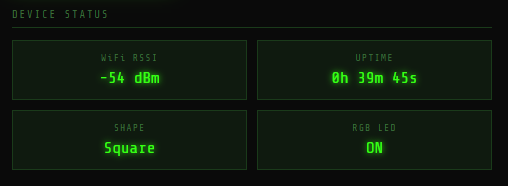
SHAPE DISPLAY:Square
SHAPE DISPLAY:Circle
SHAPE DISPLAY:Triangle
CUSTOM TEXT
CONTROLS:RGB led
CONTROLS:CLEAR OLED
DEVICE STATUS: The web page displays WiFi signal strength (RSSI), device operating time, current display mode and LED status in real time
Demo_12_BLE_LR2021
Programme Description
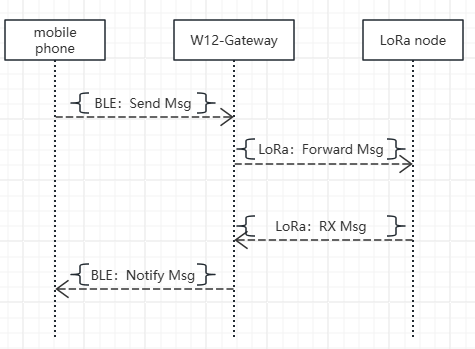
The BLE Bluetooth + LoRa wireless gateway functionality of the W12 development board enables a mobile phone to control LoRa data transmission via BLE and to relay received LoRa data back to the phone via BLE, thereby achieving bidirectional transparent transmission and enabling wireless relaying without the need for a network connection.
Key features include:
-
Initialise the BLE server with the device name W12-Gateway and wait for a mobile phone to connect
-
The mobile phone sends data via BLE; the device automatically receives it and forwards it via the LoRa module
-
Monitors LoRa wireless data in real time and automatically pushes it to your mobile phone via BLE upon receipt
-
The OLED screen displays the following in real time: BLE connection status, LoRa transmission and reception counts, latest messages, and status information
-
Built-in LoRa parameter configuration: 915 MHz band, 125 kHz bandwidth, SF7, synchronisation word 0x34
-
Serial synchronous output of BLE and LoRa transmission and reception logs for easy debugging
-
Automatically switch on the VEXT power supply to power the OLED, completing screen initialisation and status refresh
-
Automatically restart broadcasting after a BLE disconnection to ensure the gateway remains continuously available
Flowchart
Hardware connections
- Connect the board to the computer using a USB cable
Performance
-
Upon power-up, the OLED display initialises and the LoRa module and BLE services start automatically.
-
BLE broadcasts under the name W12-Gateway and waits for a mobile phone to connect
-
Once the mobile phone has connected to BLE, the OLED display shows that BLE is connected and the gateway enters standby mode
-
The mobile phone sends data via BLE; the W12 receives it and transmits it via LoRa
-
Upon receiving LoRa data, the W12 automatically transmits it back to the mobile phone via BLE
-
OLED display showing real-time updates on BLE status, LoRa transmission and reception counts, and the latest messages
-
Serial synchronous printing of BLE and LoRa transmission/reception data and status information
-
After a BLE disconnection, the device automatically resumes broadcasting, whilst LoRa continues to monitor for incoming signals
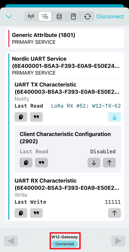
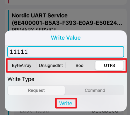
You can search for and download the nRF Connect app from the major mobile app stores; this app allows your mobile phone to search for and connect to Bluetooth devices.
- Android:nRF Connect
- IOS:nRF Connect
Connecting via Bluetooth using the app
Click this button to send the data

You can select the data type you wish to send
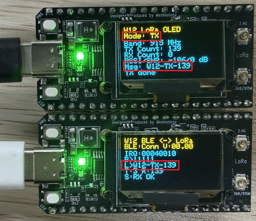
You can then view the data that has been received on the device (top: LoRa node; bottom: W12 Gateway)
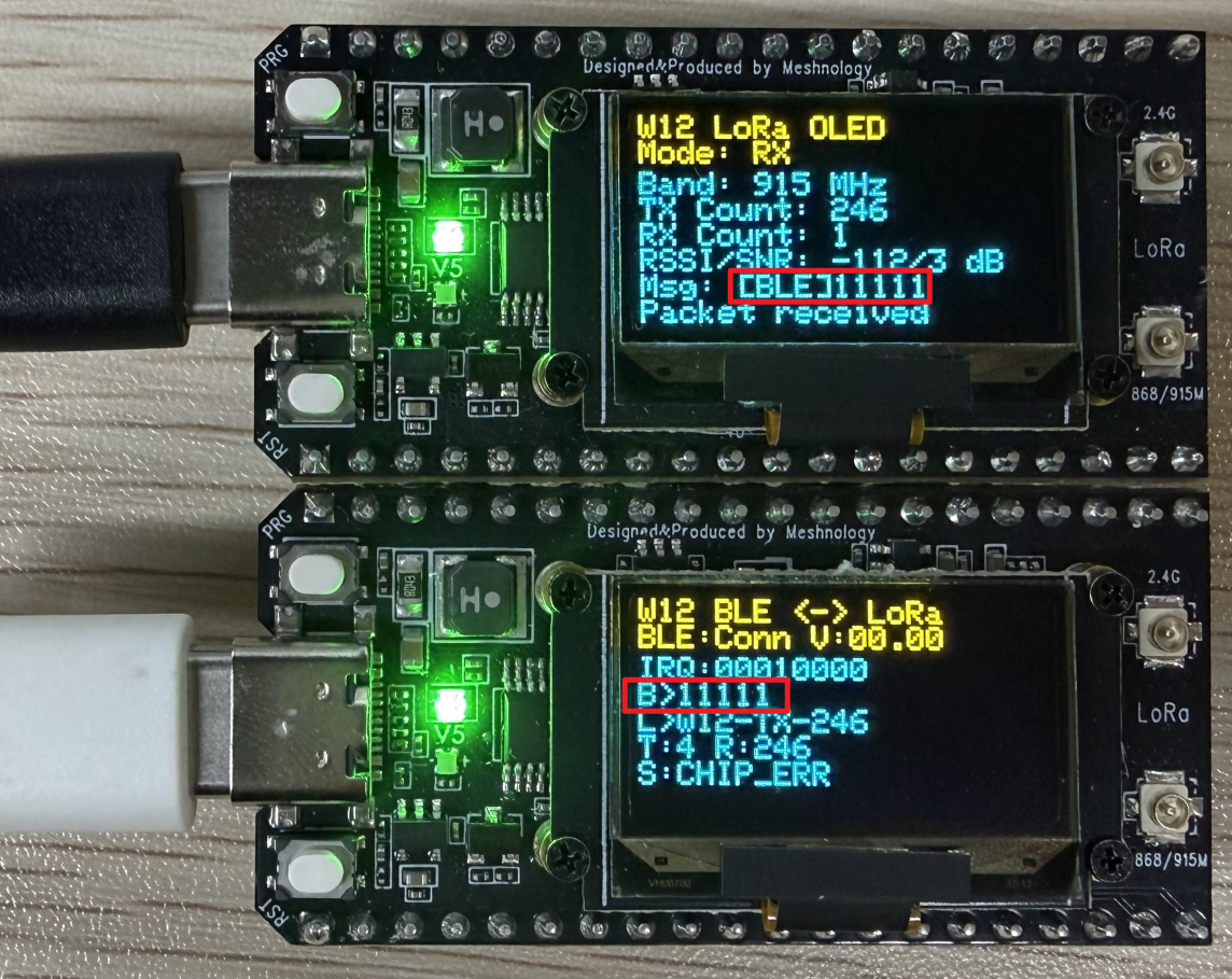
Receive data transmitted by LoRa nodes
Demo_13_GNSS_L76K
Programme Description
This programme demonstrates the standard positioning data parsing and display functions of the W12 development board when connected to an external L76K GNSS module. It can automatically receive satellite signals, parse NMEA protocol data, and output positioning information in real time to the serial port and OLED screen, operating independently and reliably without the need for additional configuration.
Key features include:
-
Ensure the L76K module is powered by the automatic control system, and correctly configure the operating states of the GNSS control pin, reset pin, wake-up pin and PPS (pulses per second) pin.
-
Initialise serial port 2 for communication with the L76K module; the default baud rate is 9600 with 8N1, and raw NMEA data from the satellite is received in real time.
-
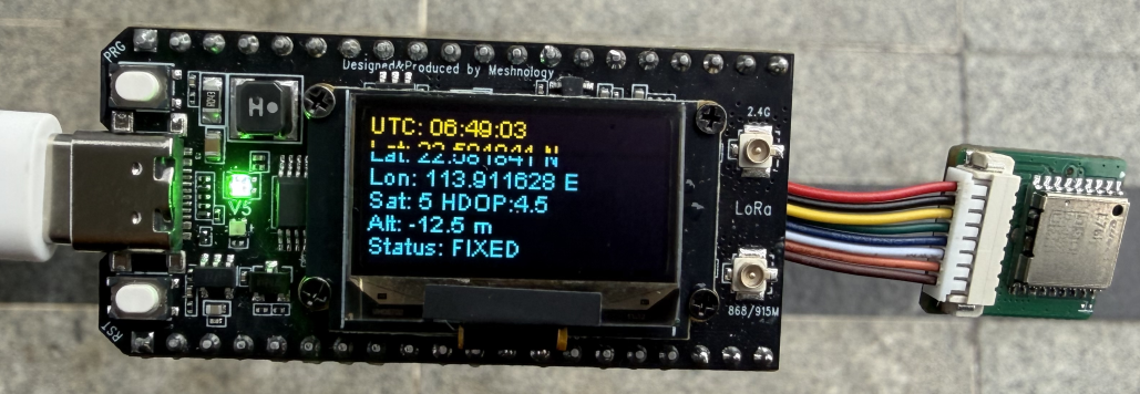
Using the TinyGPS++ library to fully parse satellite information, including UTC time, latitude and longitude, positioning status, number of satellites, horizontal accuracy factor and altitude
-
Automatically detects positioning status, with the screen and serial port displaying FIXED (positioned) or NO FIX (not positioned)
-
Data such as latitude, longitude, time and altitude is formatted, with invalid data automatically displayed as "--" to ensure a clean interface
-
The OLED screen displays complete positioning information in real time, including UTC time, latitude, longitude, number of satellites, HDOP, altitude and status
-
The screen and serial port data are refreshed once per second to ensure real-time information
-
Automatically switch on the external power supply to power the OLED screen, and complete screen initialisation, screen clearing, text rendering and screen refresh
-
A list of fully parsed positioning data is output via the serial port, facilitating debugging, log viewing and data verification
Hardware connections
- Connect the board to the computer using a USB cable
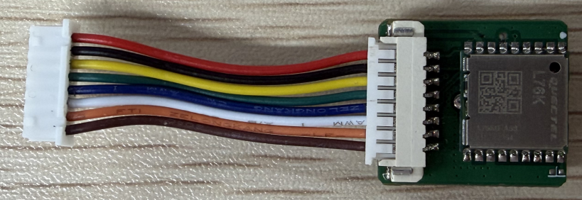
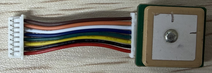
- Connect the L76K module to the board using an 8-pin adapter cable
Performance
-
During normal outdoor operation, the OLED screen and the serial port simultaneously display the ‘FIXED’ status, indicating that the unit has acquired a fix.
-
Real-time display of UTC time, latitude and longitude, bearing, number of satellites, HDOP accuracy, and altitude
-
All data is automatically refreshed once per second, ensuring reliable and accurate information
-
Once positioning is successful, the PPS pin on the GNSS module outputs a 1 Hz second pulse signal
Comprehensive Routine
Programme Description
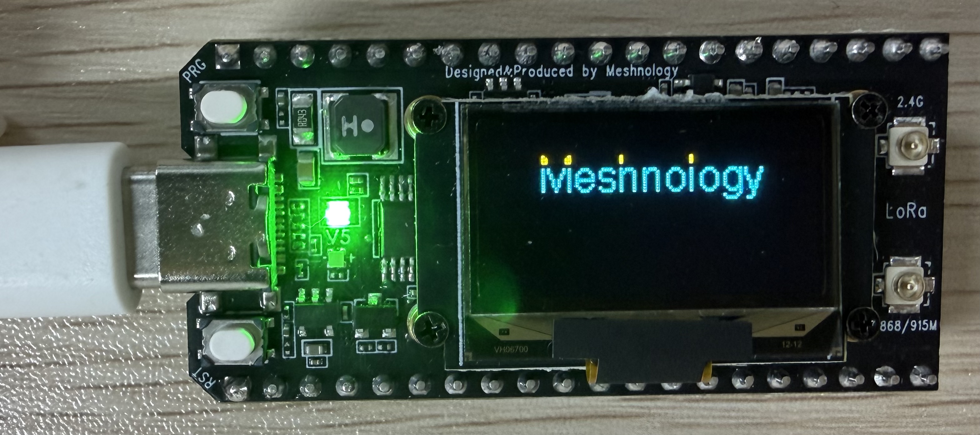
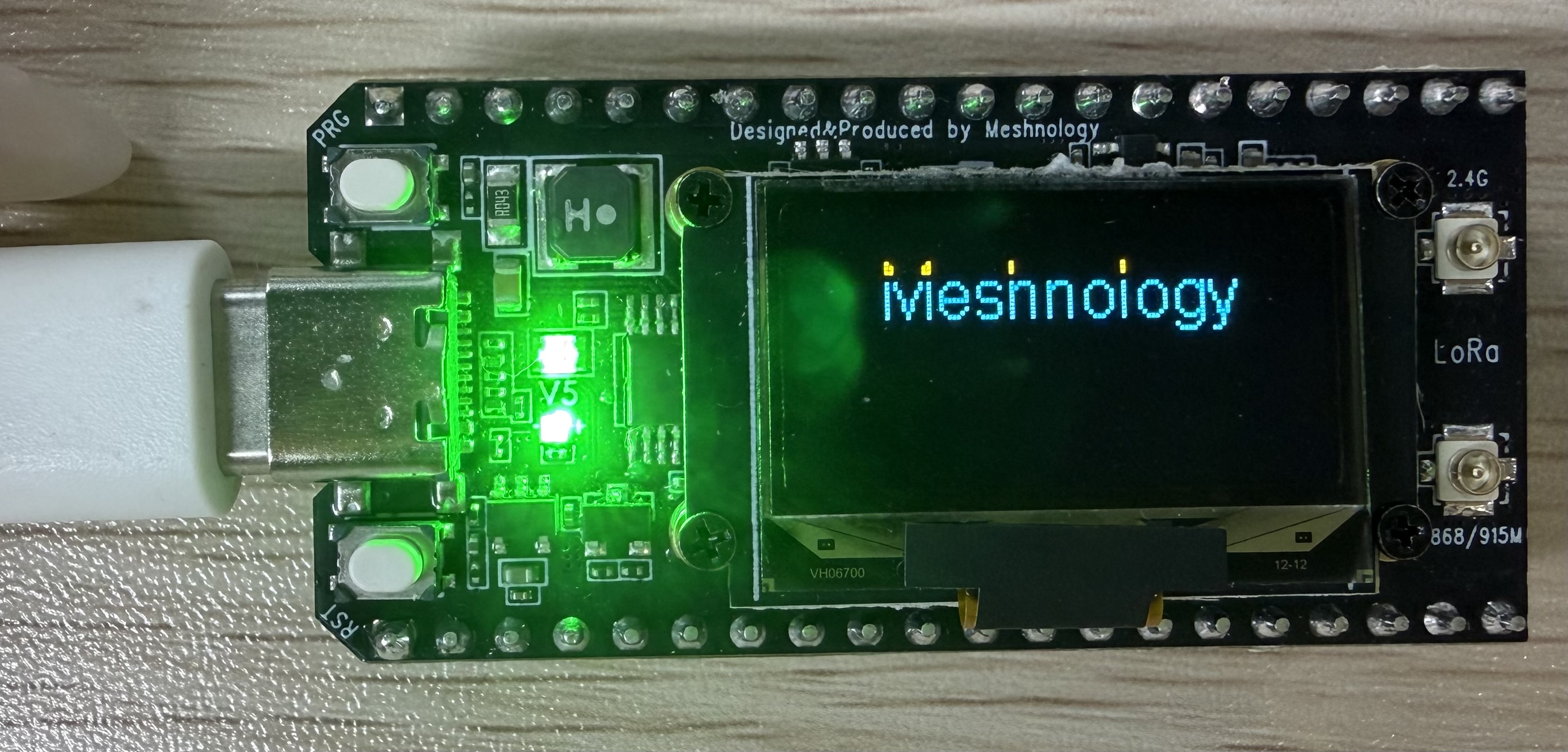
This demonstrates the comprehensive functionality of the W12 (LR2021 Ultra Long Range LoRa Device) development board, sequentially performing five key tests: boot-up logo, RGB lighting effects, I2C bus scan, Wi-Fi scan and continuous LoRa transmission and reception.
The entire process is displayed visually on the OLED screen, allowing hardware testing to be carried out independently without the need for a computer. (As the L76K module is not sold as part of this package, this functionality has not been included; please refer to the previous test programme to add it yourself.)
Key features include:
-
Automatic assembly-line factory testing upon power-up: LOGO display → RGB LED → I2C scan → WiFi scan → LoRa transmission and reception
-
The VEXT power supply is automatically activated to power the OLED; upon start-up, the W12 brand logo and chip ID are displayed.
-
RGB LED testing: automatic verification of all functions, including red/green/blue colour cycling, rapid flashing and breathing effects
-
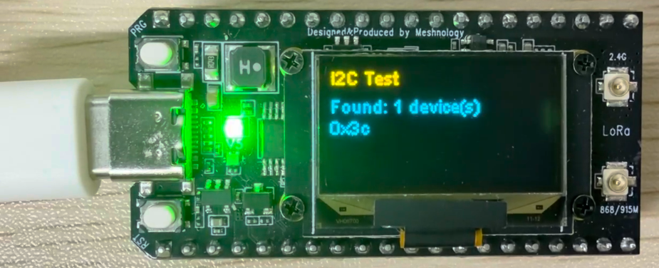
I2C bus scan: Automatically detects the addresses of all devices on the bus; the OLED displays the number of devices found and their addresses
-
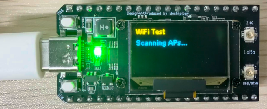
WiFi scan: Automatically searches for nearby WiFi hotspots, displaying the hotspot name, signal strength (RSSI) and the number of hotspots found
-
LoRa module initialisation: Automatic configuration of the LR2021 chip, supporting eight international frequency bands (CN/US/EU/KR/AU/NZ/AS/2.4G)
-
LoRa phase continuous transmit-and-receive: Test packets are sent every 2 seconds, whilst simultaneously monitoring incoming data in real time
-
LoRa button operations: Press the BOOT button briefly to cycle through the frequency bands; press and hold (>2 seconds) to confirm the current frequency band
-
Outside the LoRa test phase, press and hold BOOT: the device automatically enters deep sleep mode; supports wake-up after 10 minutes or via button press
-
OLED display showing real-time test status, LoRa parameters, transmission and reception counts, RSSI/SNR signal quality and the latest data
-
Serial port synchronous output of complete test logs, LoRa transmission and reception data, and hardware status, facilitating debugging and troubleshooting on the production line
-
The entire process runs automatically without the need for manual intervention; once complete, it enters LoRa continuous communication mode and remains on standby.
Hardware connections
- Connect the board to the computer using a USB cable
Performance
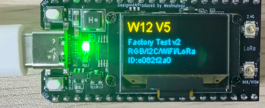
LOGO display
Version and Testing Features
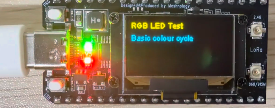
RGB LED Test - Basic colour cycle
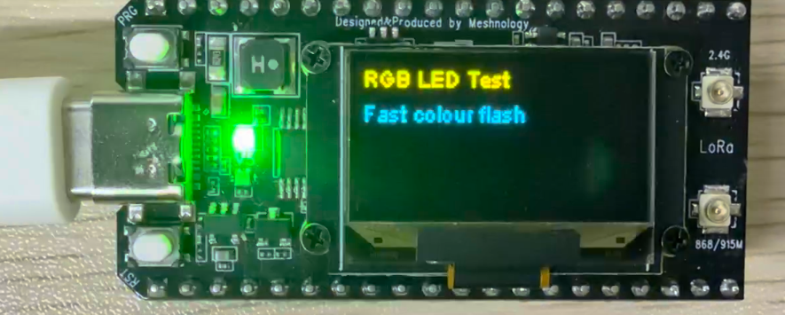
RGB LED Test - Fast colour flash
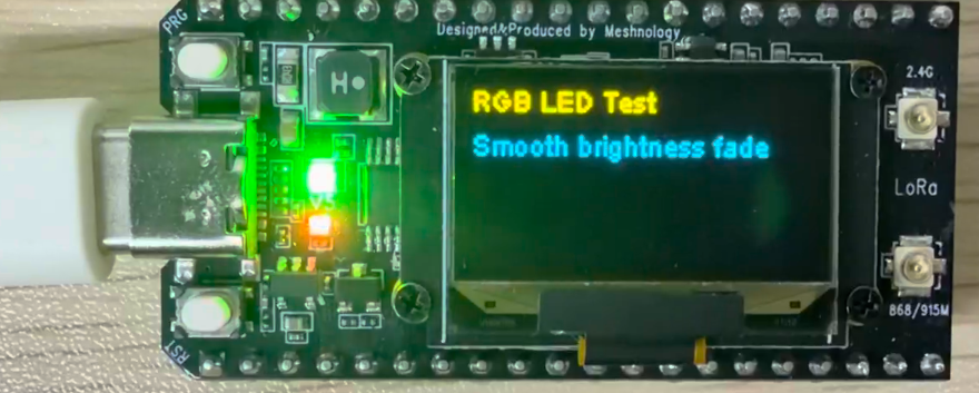
RGB LED Test - Smooth brightness fade
RGB LED Test - Breathing effect
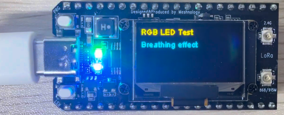
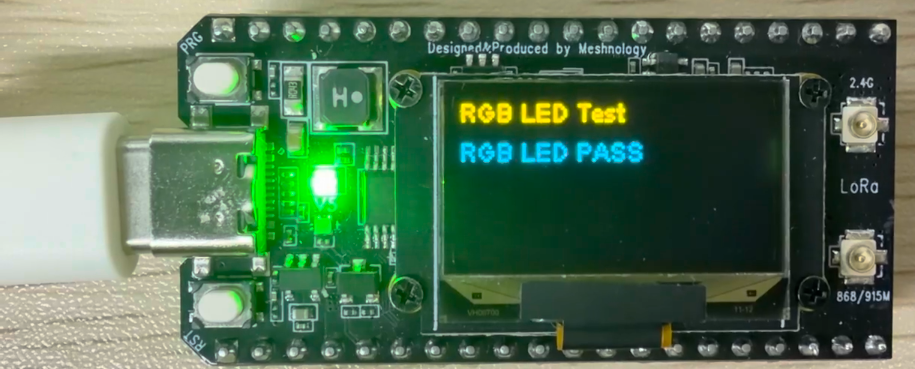
RGB LED Test - RGB LED PASS
I2C Test
WiFi Test
LoRa Test - TX - 915 MHz band (In LoRa mode, transmission and reception can occur simultaneously)
Frequency band:
CN470 490000000UL
US915 915000000UL
EU868 868000000UL
KR920 920000000UL
AU915 915200000UL
NZ915 915200000UL
AS923 923200000UL
2.4G 2405000000UL
LoRa Test - RX - 915频段
Resource downloads
Arduino deme:
Flashing tool:
Hardware specifications: