W15 ESP32-S3 LR2021 Dev Kit
The W15 combines an ESP32-S3 controller, an LR2021 radio, Wi-Fi, Bluetooth Low Energy, an OLED display, and accessible GPIO headers. This guide covers the hardware, Arduino IDE setup, firmware flashing, and the included examples.
Important: Connect the correct antenna before transmitting. Select only frequencies permitted in your region. GPIO uses 3.3 V logic and must not be connected directly to 5 V signals.
Product overview
Product introduction
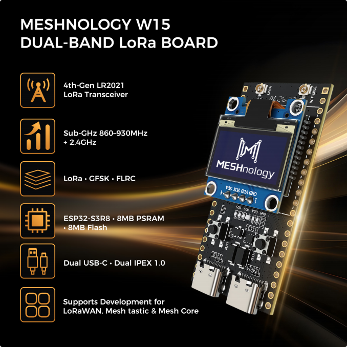
The ESP32-S3 LR2021 DEV KIT development board is a developer hardware platform designed to combine LoRa, Wi-Fi, and BLE connectivity for IoT development: "one board for remote
monitoring + high-speed cloud connectivity + local O&M".
The product is equipped with the ESP32-S3R8 main controller and the LR2021 radio, and supports dual-band Sub-GHz and 2.4GHz LoRa communication. It integrates Wi-Fi and Bluetooth, and is suitable for a wide range of application scenarios such as industrial IoT, smart agriculture, smart cities, and outdoor communication.
Product image
Target applications
-
Industrial IoT: temperature and humidity monitoring, circuit monitoring, vibration monitoring, gateway data transmission, device control
-
Smart Agriculture: soil moisture monitoring, temperature/humidity/light monitoring, livestock positioning, irrigation valve control
-
Smart Security: infrared monitoring, vibration monitoring, inspection wristband positioning, camera intrusion monitoring
-
Smart City: streetlight control, PM2.5 monitoring, noise monitoring, data aggregation to the cloud
-
Outdoor Communication: earthquake rescue communication, photovoltaic power generation monitoring, gateway data exchange
-
Maker Education: teaching course practice, smart environment monitoring models, smart farm models
Specifications
Hardware specifications
Category | Parameter | Specification |
Processor & Memory | Main controller | ESP32-S3R8 |
Processor architecture | Xtensa LX7 dual-core 32-bit, 240MHz | |
RAM | 8MB PSRAM | |
Flash | 8MB SPI Flash | |
LoRa chip | LR2021 radio transceiver | |
Wi-Fi Specifications | Standard | IEEE 802.11 b/g/n (@2.4 GHz) |
Frequency band | 2.4GHz | |
Channel | 2.4 GHz: Ch1 ~ Ch13 | |
Modulation | 802.11b: DQPSK, DBPSK, CCK; 802.11g/n OFDM: 64-QAM, 16-QAM, QPSK, BPSK | |
Transmission range | Indoor ≥50m, open environment ≥100m | |
Packet loss rate | ≤1% (at 80m) | |
Bluetooth Specifications | Wireless standard | Bluetooth 5.0 (BLE) |
Operating frequency | 2.4GHz | |
Channel | LE: Ch0 ~ Ch39 | |
Modulation | GFSK | |
Transmit power | -24 ~ 20 dBm | |
Maximum input level | 8 dBm, Typical | |
Transmission range | Indoor ≥ 32 m, open environment ≥ 80 m | |
LoRa Specifications | Supported bands | Sub-GHz (860–930 MHz) + 2.4 GHz dual band |
Category | Parameter | Specification |
Modulation | LoRa / GFSK / FLRC | |
Sub-GHz transmit power | Max 22dBm | |
2.4GHz transmit power | Max 8dBm (This version has not been optimized 2.4 GHz RF matching; the module's measured maximum transmission power is 8 dBm) | |
Receiver sensitivity | Down to -141.5 dBm | |
FLRC high-speed mode | Up to 2.6 Mbps | |
Sub-GHz transmission range | Open area ≥5 km, urban ≥1 km | |
2.4GHz transmission range | TBD | |
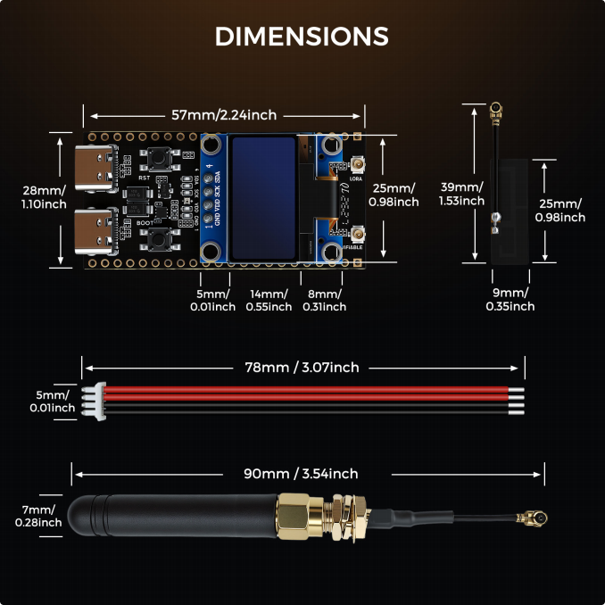
Physical Characteristics | Board dimensions | 57 × 28 × 1.6 mm |
Enclosure dimensions | 73.0 × 49.2 × 30.0 mm | |
Overall height (incl. LoRa antenna) | 186 mm | |
Weight (single board) | Approx. 12g | |
PCB material | FR-4, 1.6mm thickness | |
PCB process | ENIG (immersion gold) process, improving oxidation resistance and soldering reliability | |
Pin process | Gold-plated, insertion/removal life ≥1000 cycles | |
External Interfaces | USB interface | 2 × Type-C (power supply, firmware flashing, serial debugging) |
Antenna interface | 2 × IPEX 1.0 (Wi-Fi antenna, LoRa antenna) | |
Reset button | 1 × RST button (hardware reset) | |
Boot button | 1 × BOOT button (download mode / user- defined) | |
LED indicator | 1 × user-programmable LED | |
Expanded GPIO | 26 multiplexable GPIO pins | |
Battery interface | Supports lithium battery charging | |
Peripheral Support | GPIO multiplexing | ADC, I2C, I2S, SPI, UART, PWM |
Category | Parameter | Specification |
Electrical Characteristics | Supply voltage | 5V (USB Type-C powered) |
Operating voltage | 3.3V | |
Maximum I/O output current | Single pin ≤20mA, total I/O current ≤100mA | |
Charging efficiency | ≥85% (lithium battery charging) | |
Startup time | ≤1 second (from power-off to normal operation) | |
Operating temperature | -40℃ ~ 85℃ (industrial grade) | |
Storage temperature | -40℃ ~ 125℃ | |
Operating humidity | 10% ~ 90% RH (non-condensing) | |
Reliability Metrics | Mean time between failures (MTBF) | ≥20,000 hours |
ESD protection | Contact discharge ±8 kV, air discharge ±15 kV | |
Vibration resistance | 10~2000 Hz, 10g acceleration | |
Shock resistance | 1000g, 0.5 ms half-sine wave | |
Compliance & Certification | Wireless certification | CE (EN 300 328), FCC Part 15B/15C |
Electrical safety | IEC 62368-1 | |
Environmental standards | RoHS 2.0, REACH | |
EMC | Complies with CE EN 300 328, FCC Part 15B standards | |
Antenna Configuration | 2.4G FPC high-gain antenna | 2dBi / Wi-Fi·BLE communication, built-in/on-board |
LoRa rubber-duck antenna | 2dBi / Sub-G·2.4G dual band, general outdoor communication |
Software support
Development frameworks
-
Arduino IDE: Beginner-friendly, with a dedicated core library
-
ESP-IDF v5.0+: Professional development framework, supports multitasking and low-power configuration
-
MicroPython: Script-based programming, ideal for rapid prototyping
-
PlatformIO: Integrated into VS Code, supports remote compilation
-
RT-Thread RTOS: Industrial-grade real-time operating system
Protocol support
-
LoRaWAN 1.0.2/1.1 (Class A/B/C)
-
Meshtastic 2.0 / MeshCore (self-organizing mesh protocols)
-
TCP/UDP/HTTP(S)/MQTT/MQTT-SN full-stack network protocols
-
CoAP (lightweight IoT protocol)
-
LoRa Edge geolocation protocol
Pinout
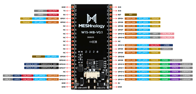
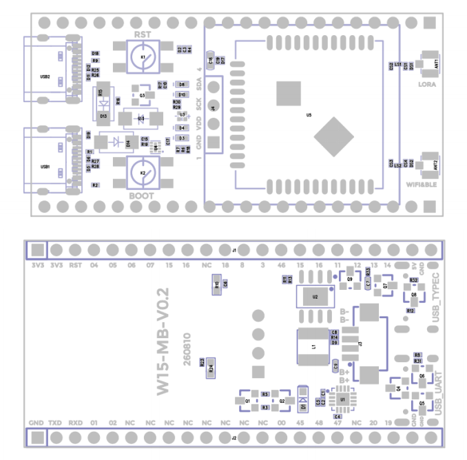
1. Expanded IO ports: from bottom-left to bottom-right
No. | Name | Definition |
1 | GND | — |
2 | TXD | U0TXD/GPIO43/CLK_OUT1 |
3 | RXD | U0RXD/GPIO44/CLK_OUT2 |
4 | GPIO01 | RTC_GPIO1/GPIO1/TOUCH1/ADC1_CH0 |
5 | GPIO02 | RTC_GPIO2/GPIO2/TOUCH2/ADC1_CH1 |
6 | NC | — |
7 | NC | — |
No. | Name | Definition |
8 | NC | — |
9 | NC | — |
10 | NC | — |
11 | NC | — |
12 | NC | — |
13 | NC | — |
14 | GPIO00 | RTC_GPIO0/GPIO0/BOOT |
15 | GPIO45 | GPIO45 |
16 | GPIO48 | SPICLK_N_DIFF/GPIO48/SUBSPICLK_N_DIFF |
17 | GPIO47 | SPICLK_P_DIFF/GPIO47/SUBSPICLK_P_DIFF |
18 | NC | — |
19 | GPIO20 | RTC_GPIO20/GPIO20/U1CTS/ADC2_CH9/CLK_OUT1/USB_D+ |
20 | GPIO19 | RTC_GPIO19/GPIO19/U1RTS/ADC2_CH8/CLK_OUT2/USB_D- |
21 | GND | — |
22 | GND | — |
2. Expanded IO ports: from top-left to top-right
No. | Name | Definition |
1 | 3V3 | — |
2 | 3V3 | — |
3 | RST | RST/CHIP_UP |
4 | GPIO04 | RTC_GPIO4/GPIO4/TOUCH4/ADC1_CH3 |
5 | GPIO05 | RTC_GPIO5/GPIO5/TOUCH5/ADC1_CH4 |
6 | GPIO06 | RTC_GPIO6/GPIO6/TOUCH6/ADC1_CH5 |
7 | GPIO07 | RTC_GPIO7/GPIO7/TOUCH7/ADC1_CH6 |
8 | GPIO15 | RTC_GPIO15/GPIO15/U0RTS/ADC2_CH4/XTAL_32K_P |
9 | GPIO16 | RTC_GPIO16/GPIO16/U0CTS/ADC2_CH5/XTAL_32K_N |
10 | NC | — |
11 | GPIO18 | TC_GPIO18/GPIO18/U1RXD/ADC2_CH7/CLK_OUT3 |
12 | GPIO08 | RTC_GPIO8/GPIO8/TOUCH8/ADC1_CH7/SUBSPICS1 |
13 | GPIO03 | RTC_GPIO3/GPIO3/TOUCH3/ADC1_CH2 |
No. | Name | Definition |
14 | GPIO46 | GPIO46 |
15 | GPIO09 | RTC_GPIO9/GPIO9/TOUCH9/ADC1_CH8/FSPIHD/SUBSPIHD |
16 | GPIO10 | TC_GPIO10/GPIO10/TOUCH10/ADC1_CH9/FSPICS0/FSPIIO4,SUBSPICS |
17 | GPIO11 | TC_GPIO11/GPIO11/TOUCH11/ADC2_CH0/FSPID/FSPIIO5/SUBPID |
18 | GPIO12 | TC_GPIO12/GPIO12/TOUCH12/ADC2_CH1/FSPICLK/FSPIIO6,SUBSPICL |
19 | GPIO13 | TC_GPIO13/GPIO13/TOUCH13/ADC2_CH2/FSPIQ/FSPIIO7/SUBSPIQ |
20 | GPIO14 | TC_GPIO14/GPIO14/TOUCH14/ADC2_CH3/FSPIWP/FSPIDQS,SUBSPIW |
21 | 5V | — |
22 | GND | — |
Dimensions
Mechanical drawing
Getting started
Hardware requirements
- W15 ESP32-S3 LR2021 development kit
Software requirements
-
Arduino IDE, flash_download_tool
-
You can also develop using the ESP-IDF plugin in VS Code
Arduino IDE setup
Set up the development environment
Install Arduino IDE
Arduino download site: arduino.cc/en/software
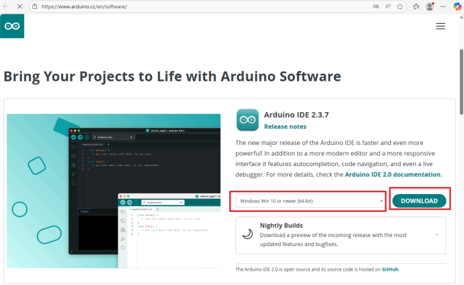
Download and install the software following the Arduino installation instructions
Install the ESP32 board package
-
To use ESP32-based boards in the Arduino IDE, you must first install the “esp32 by Espressif Systems” board package.
-
Install in accordance with the panel installation requirements. Once you have opened the software
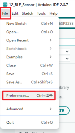
Add the address of the development board manager
- Link to the stable release:
https://espressif.github.io/arduino-esp32/package_esp32_index.json
- Link to the development version:
https://espressif.github.io/arduino-esp32/package_esp32_dev_index.json
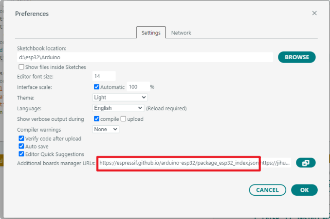
When you have finished, select OK
-
Select the Board Manager on the left-hand side of the software
-
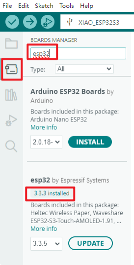
Search for 'esp32' in the search bar
-
In the version field for the ‘esp32 by Espressif Systems’ development board found in the search results, select a version of 3.2.0 or higher
-
Click to install
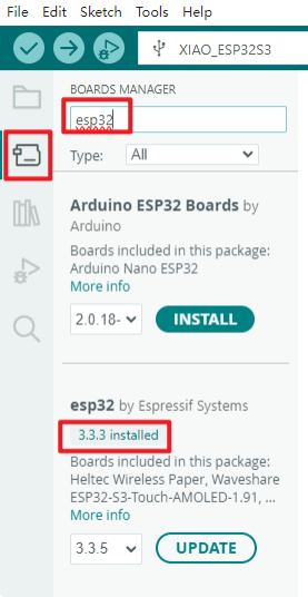
- Once you click it, a message like this will appear in the bottom-right corner of the software; please wait for the download to complete (ensure you have a stable internet connection).
while waiting).
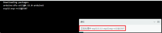
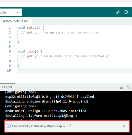
- Once the download is complete, a success message will appear
- When you search again, the word ‘installed’ will appear
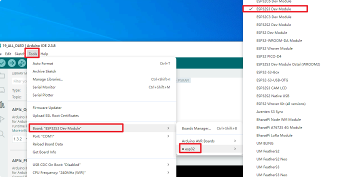
Select the board
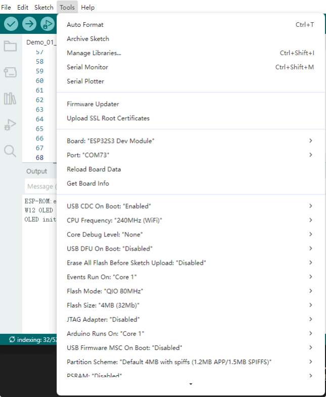
The development board is an ESP32-S3 Dev Module
Before each burn, you must check that the development board type is correct.
Configure the board parameters
Install the required libraries
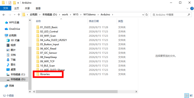
When installing Arduino libraries, there are usually two options available: online installation and offline installation. If a library requires offline installation, you must use the provided library files. For most libraries, users can easily search for and install them via the Arduino software’s online library manager. However, some open-source or custom libraries are not synchronised with the
Arduino library manager and therefore cannot be obtained via an online search. In such cases, users must install these libraries manually using the offline method.
As the library files for this product are already included in the compressed package for the sample program, there is no need to download any additional libraries.
Example programs and firmware files
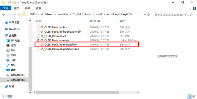
All example programs have their own .ino files, which you can modify based on the source code to achieve the expected results. There are also pre-compiled .bin files that can be flashed
directly with flash_download_tool.
The .bin files ending with "merged" in each demo's "build" folder can be flashed directly.
Flash precompiled firmware
Flash Download Tool
Download flash_download_tool, official download link:
https://dl.espressif.com/public/flash_download_tool.zip
Tool overview
Open the tool
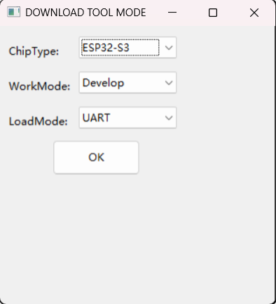
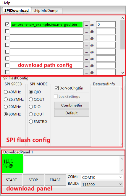
Open the Flash Download Tool; double-click the .exe file to access the main interface, as shown below:
-
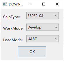
ChipType : Chip type: select according to the product type used
-
WorkMode : Software mode: there are currently two modes — Develop mode and Factory mode — the differences are as follows:
-
Develop : This mode uses the absolute path of the firmware and only supports flashing single-chip products.
-
Factory : Since this mode uses relative paths, we recommend placing the firmware to be flashed in the "bin" folder at the same level as the .exe file; when the application is closed, the configuration is automatically saved locally.
-
Factory : When opened, the interface is locked; you must click the "Lock Settings" button to enable editing. This prevents accidental mouse operations.
-
LoadMode : The download interface supports UART and USB
SPI Download interface
The following are configuration instructions:
-
Download Path Config : Include the firmware load path and download address, entered in hexadecimal format, e.g., 0x1000.
-
SPI Flash Config
-
SPI SPEED : SPI clock speed
-
SPI MODE : SPI flash mode
-
DETECTED INFO : Automatically detects flash and crystal oscillator information
-
DoNotChgBin : If enabled, the original contents of the bin file will be flashed. If
disabled, the settings will be updated and flashed according to the SPI SPEED and SPI MODE configuration on the interface.
- CombineBin button: You can bundle multiple firmware files selected in the download path configuration into a single firmware file. If DoNotChgBin is enabled, the files will be bundled as-is. If DoNotChgBin is not enabled, the firmware will be bundled
according to the SPI SPEED and SPI MODE settings on the interface. Non-data areas between firmware files are filled with 0xff. The merged firmware is saved as
.combine/target.bin; each click overwrites the previous version.
-
Default button: Resets all SPI interface settings to default values
-
Download Panel
-
START : Start button
-
STOP : Stop button
-
ERASE : Full flash erase
-
COM : Download serial port
-
BAUD : Download baud rate
Factory Multi-Download interface
- Factory : This mode uses relative paths, loading firmware by default from the bin
directory in the tool directory for flashing. The Develop mode, however, uses absolute
paths. The advantage of Factory mode is that once the firmware to be flashed is copied to the bin directory in the tool directory, it can be copied between factory computers without path issues.
- When Factory mode is enabled, LockSettings is enabled by default when the tool starts. Once enabled, neither the firmware paths nor the SPI flash config can be modified.
preventing configuration errors caused by accidental changes by production line personnel. (Factory managers who need to make configurations can click LockSettings to unlock.)
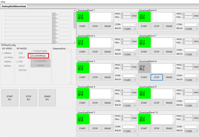
The download path config and SPI flash config settings on the FactoryMultiDownload interface are basically the same as those on the SPIDownload interface. Please refer to
SPIDownload Interface, and make sure you configure the serial port number and baud rate for each channel separately.
Chip Info Dump interface
-
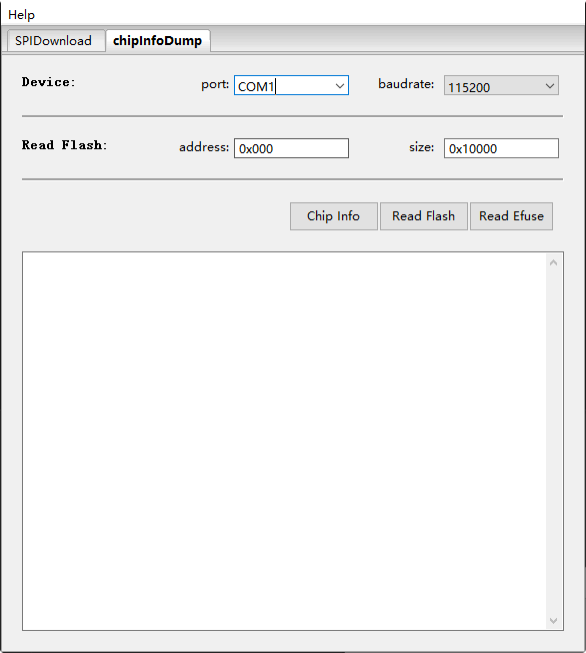
Device : Select the serial port number and baud rate of the relevant device.
-
Read Flash: Select the start address and the size of the data to read from flash. This option is set only when reading flash.
-
Function Description
-
Chip Info: Reads the chip model, flash ID, and flash status register values; the data is displayed directly on the software interface.
-
Read Flash: Reads data from flash. The read data is stored in a generated bin file with the format: "chip MAC + read data start address + read data length + read time".
-
Read eFuse: Reads the contents of the chip's eFuse; this function is the same as
ESPTOOL's summary command. The read data is stored in a generated text file with the format "chip MAC + read time".
Flashing example
This section uses the ESP32-S3 series as an example to demonstrate how to perform standard and encrypted flashing.
Standard firmware flashing
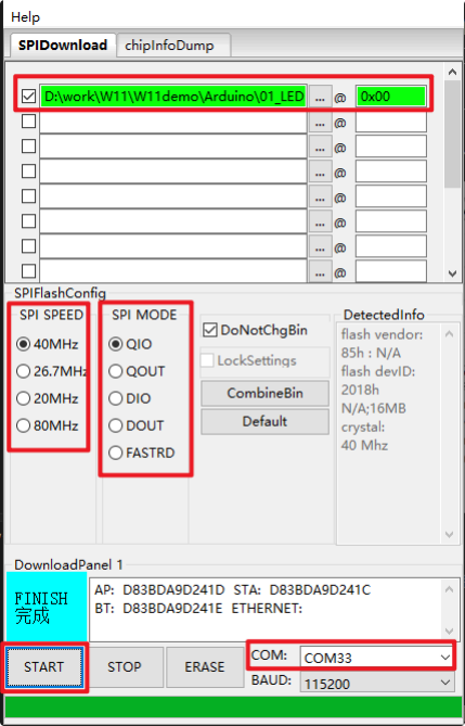
1. Pull the GPIO0 pin low to switch the device to download mode.
2. Open the download tool, select ESP32S3 for ChipType , Develop for WorkMode , UART for LoadMode , then click OK , as shown below.
3. On the download page, enter the bin file you want to flash and the corresponding flash
address, check the checkbox next to the bin file, and enter the values you require for SPI SPEED , SPI MODE , COM , and BAUD .
4. Click START to begin the download. During the download, the download tool reads the flash information and the chip's MAC address.
5. After the download completes, the download tool interface will display as shown below.
01_OLED_Basic
Overview
This demo program is designed to verify the basic functions of the OLED on the W15. After powering on, the program initializes the OLED and then loops as follows:
-
- Text display demo
-
- Basic graphics demo (rectangle, circle, line)
-
- Simple animation demo (moving square, breathing circle)
-
- Progress bar 0-100%
Hardware
-
Development board: ESP32-S3 LR2021 development kit (W15)
-
OLED: I2C, SDA=GPIO5, SCL=GPIO4, RST=GPIO38
Hardware connection
- Connect the board to the computer with a USB cable
Expected result
- The OLED screen will sequentially display text, basic shapes (rectangle, circle, line), animations (moving square, breathing circle), and a progress bar.
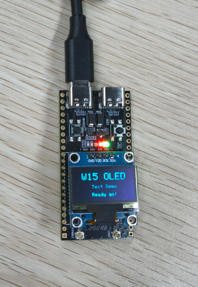
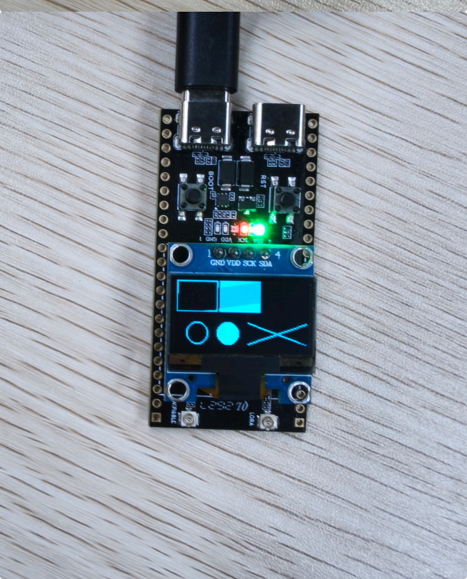
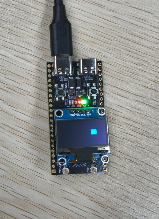
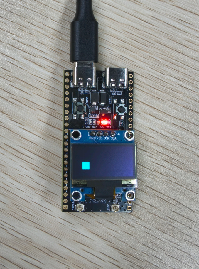
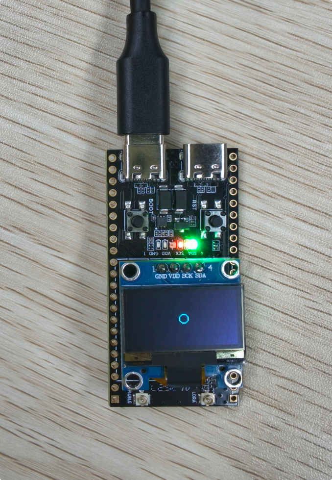
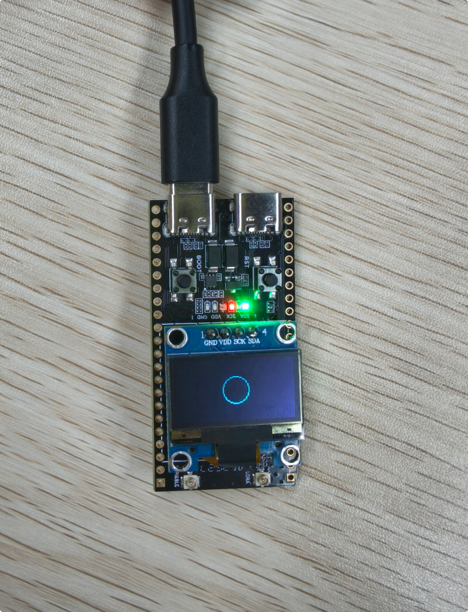
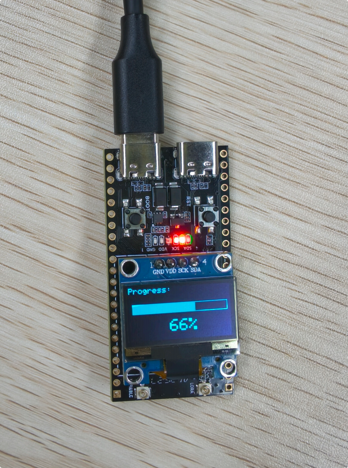
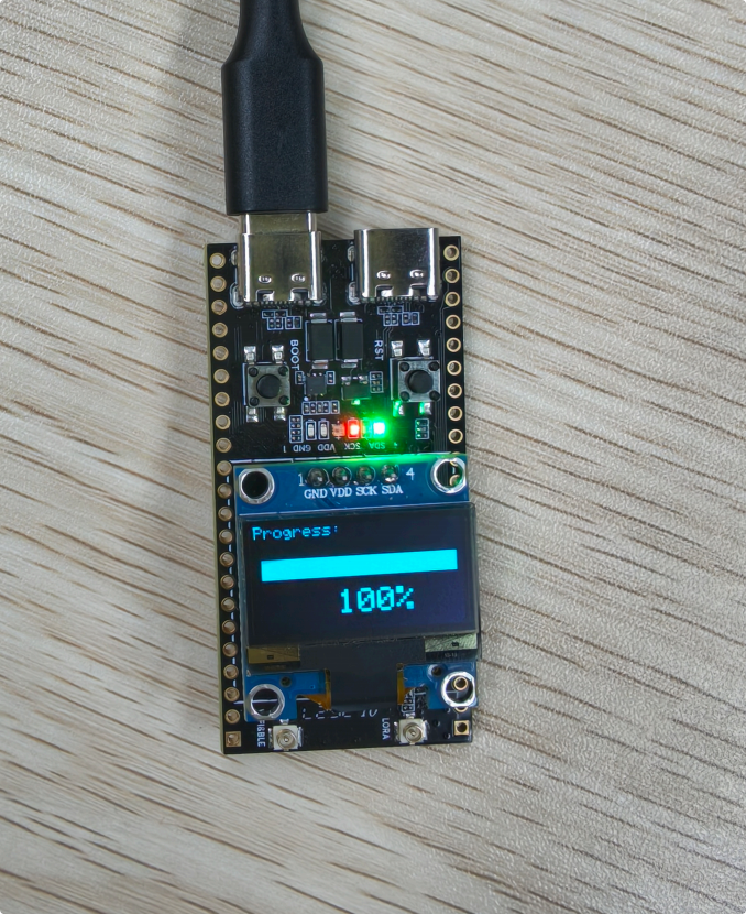
After flashing the firmware, you can view the actual results
02_LED_Control
Overview
Uses the Adafruit_NeoPixel library to drive the RGB LED connected to GPIO48,
implementing basic color cycling, fast blinking, smooth color transitions, and breathing light effects.
Main features include:
-
Initializes the single on-board RGB LED using RGB color format and an 800 kHz communication rate.
-
Cycles through the three primary colors—red, green, and blue—switching automatically every 500 milliseconds
-
Provides a fast six-color blinking effect with red, green, blue, yellow, cyan, and magenta alternating
-
Supports a smooth warm-yellow brightness gradient, with brightness gradually increasing from 0 to 255 and then decreasing back to 0
-
Creates a cyan breathing light effect, with the light blinking in a slow, rhythmic pattern
-
All light effects are displayed in an auto-cycling manner, with the current display state output via the serial port
-
Provides the standard setColor() function for easily customizing any RGB color
Hardware connection
-
Connect the board to the computer with a USB cable Performance
-
The built-in LED on the board will cycle through four different light effects
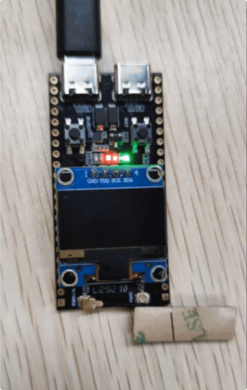
After flashing the firmware, you can view the actual results:
03_Wi-Fi_Scan
Overview
This program demonstrates the Wi-Fi scanning function of the W15. At startup, it sets the Wi-Fi to STA mode and periodically scans nearby 2.4GHz Wi-Fi networks. After each scan completes, it outputs the network list via the serial port, including:
-
SSID (network name)
-
RSSI (received signal strength indicator)
-
Encryption type
-
Channel number
The program automatically repeats the scan every 5 seconds, allowing you to monitor changes in the surrounding Wi-Fi environment in real time.
Hardware connection
- Connect the board to the computer with a USB cable
Expected result
-
Open the serial monitor at a baud rate of 115200
-
View all Wi-Fi information detected by the device
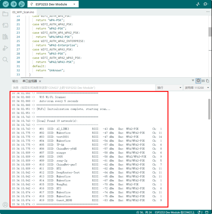
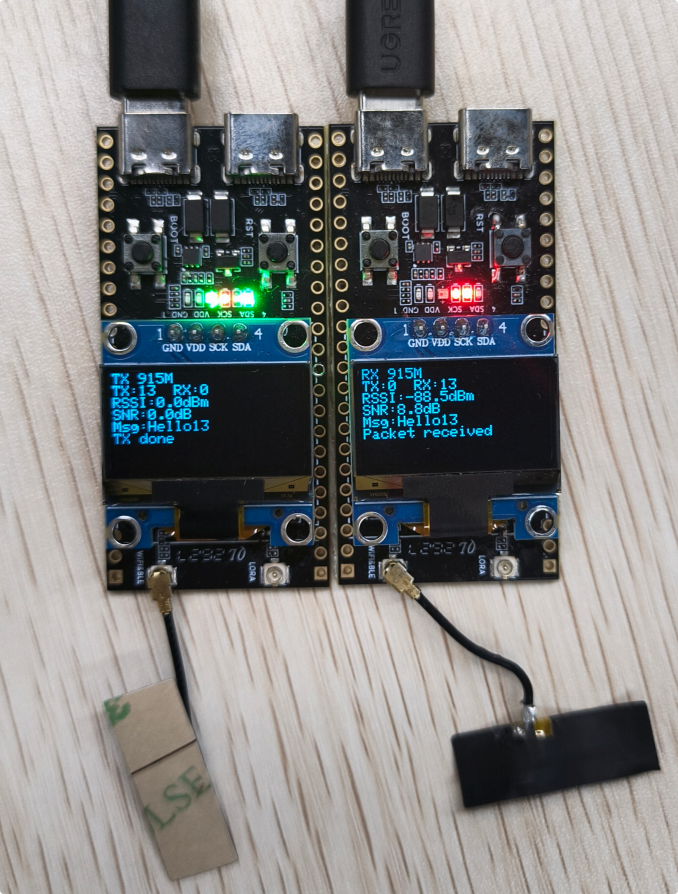
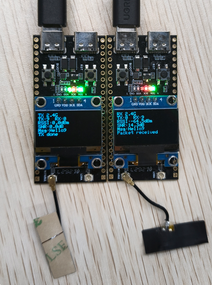
04_LoRa_OLED_LR2021
Overview
This demonstrates the LoRa wireless transceiver function of the W15 development board,
supporting one-key switching between transmit and receive modes, and flexible frequency
switching, and an OLED display showing status and data in real time. It can run independently without connecting to a computer.
Main features include:
-
At startup, the device defaults to LoRa receive mode, continuously monitoring wireless data over the air
-
Short-press the BOOT button to switch between frequency bands (868MHz/915MHz/2.4GHz, etc.).
-
Long-press the BOOT button to switch between receive (RX) and transmit (TX) modes
-
In TX mode, a data packet containing a transmission sequence number is automatically sent every second
-
In RX mode, received packets are automatically parsed, displaying signal strength (RSSI) and signal-to-noise ratio (SNR)
-
The OLED screen displays the following in real time: operating mode, frequency band, transmit/receive counts, signal strength, and the latest message
-
The serial port synchronously outputs transmission and reception logs, data content, and RSSI/SNR parameters for easy debugging
-
Pre-configured standard LoRa parameters ensure reliable communication with other LoRa devices.
Hardware connection
- Connect the board to the computer with a USB cable
Expected result
Actual appearance
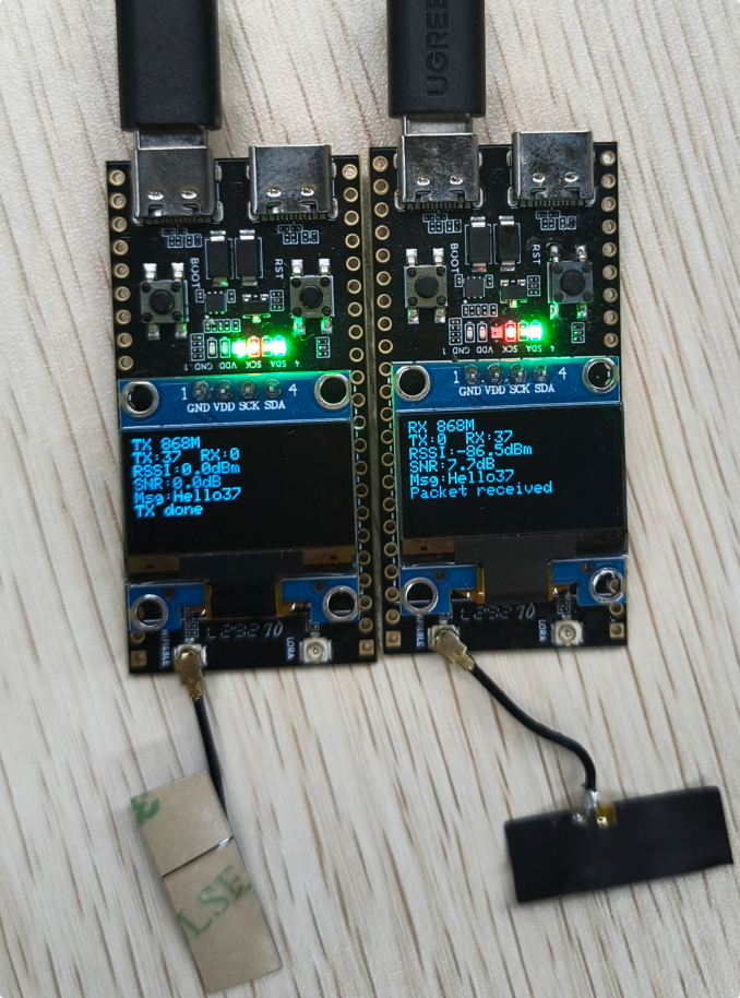
05_Button_Input
Overview
The on-board BOOT button (GPIO0) is used to detect short and long presses, with the RGB LED providing visual feedback; the system also includes button debouncing and safe interrupt handling.
Main features include:
-
Uses an interrupt-based approach for button detection, ensuring fast response without occupying main loop resources
-
Built-in 50-millisecond button debouncing effectively prevents false triggering caused by voltage fluctuations
-
Automatically detects two operation modes: short press of less than 1000 milliseconds and long press of 1000 milliseconds or more
-
On short press, the RGB LED cycles through eight colors (red, green, blue, yellow, cyan, magenta, white, and off).
-
On long press, the RGB LED automatically switches to a cyan breathing light effect; long-press again to exit
-
Real-time serial output of key type, press duration, cumulative count, and current LED color
-
The button uses an internal pull-up configuration, requiring no external circuitry; just use the on-board BOOT button.
-
The interrupt service routine (ISR) is decorated with IRAM_ATTR to ensure running stability
Hardware connection
- Connect the board to the computer with a USB cable
Expected result
-
Open the serial monitor
-
Press the BOOT button to switch the LED on and off
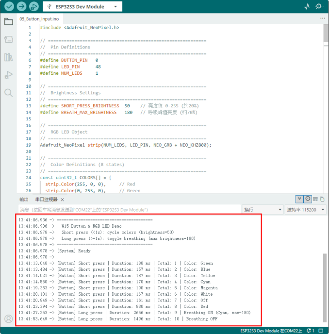
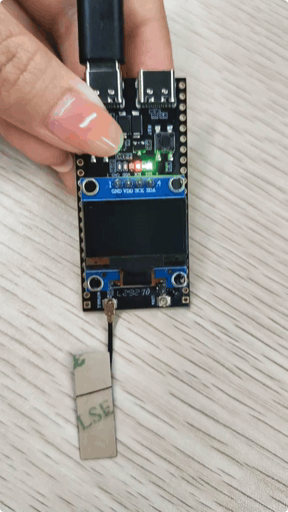
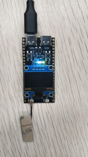
After flashing the firmware, you can view the actual results:
06_ADC_Read
Overview
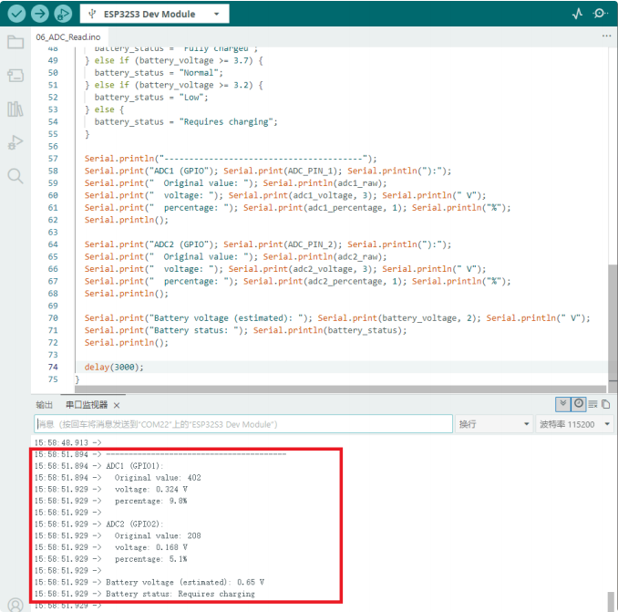
This project demonstrates the ADC analog acquisition capability of the W15. It periodically
reads data from two ADC channels (GPIO1 and GPIO2), reduces noise by averaging multiple samples, and outputs the results to the serial port as voltage values and percentages.
Main features include:
-
Configures 12-bit ADC resolution with 11 dB attenuation (approx. 0–3.3 V range)
-
Dual-channel sampling with averaging filter
-
Raw value, voltage value, and percentage display
-
Estimates battery voltage based on voltage divider assumptions, outputting charge status (fully charged / normal / low / needs charging)
Hardware connection
- Connect the board to the computer with a USB cable
Expected result
-
Dual-channel ADC sampling (10-point averaging)
-
Raw value, voltage, and percentage display
-
Battery voltage estimation and status assessment
07_I2C_Sensor
Overview
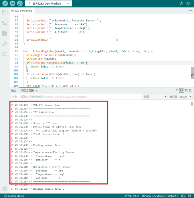
By powering external sensors, initializing the I2C bus, scanning all devices on the bus, and providing a framework for reading common sensor data such as temperature, humidity, and pressure, the system can quickly identify and integrate various I2C sensors.
Main features include:
-
Controls the VEXT power supply to power external I²C sensors, ensuring proper hardware operation
-
Initializes the I2C bus (SDA: 17 / SCL: 18), supporting the standard 100 kHz communication rate
-
Automatically scans all slave addresses on the I2C bus, identifying common devices (OLED, AHT20, SHT31, BMP280, etc.)
-
Provides a framework for reading temperature, humidity, and pressure sensor data, facilitating integration with real-world sensor libraries
-
Encapsulates utility functions for reading and writing generic I2C registers, which can be used directly in various I2C device drivers
-
Periodically outputs sensor data; supports polling every 2 seconds
Hardware connection
-
Connect the board to the computer with a USB cable
-
If you need to attach a sensor, you can use this program to check whether the sensor is correctly connected.
Expected result
08_DeepSleep
Overview
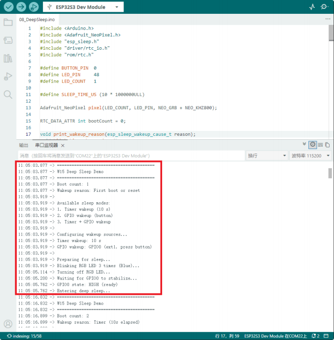
This program implements timer wake-up, GPIO button wake-up, and a combination of both wake-up sources. Upon waking, it displays a visual signal via the RGB LED while turning off external power to reduce power consumption.
Main features include:
-
Uses RTC memory to store the variable recording the number of system boots; the data remains unchanged during deep sleep
-
Automatically detects and prints the wake-up reason (timer, GPIO button, first boot, or reset)
-
Supports a 10-second automatic wake-up timer
-
Supports manual wake-up via GPIO0 (BOOT button)
-
Adopts a dual wake-up source mode combining timer and button; the device wakes up when either condition is met
-
Upon waking, the RGB LED flashes blue three times as an indicator
-
Turns off the RGB LED before entering sleep mode to optimize power efficiency
-
Outputs complete sleep status, wake-up information, and statistics via the serial port
-
After deep sleep, the program restarts from setup() loop() function is never executed
Hardware connection
- Connect the board to the computer with a USB cable
Expected result
09_Wi-Fi_TCP
Overview
This program demonstrates the data transmission and reception capabilities of a 2.4GHz Wi-Fi TCP server on the W15 development board. After connecting to a router, the device sets up a TCP server and waits for a client (such as a network debugging assistant) to connect, enabling bidirectional data pass-through, echo testing, and status monitoring.
Main features include:
-
Connects to the specified 2.4GHz Wi-Fi network in STA mode, automatically obtains an IP address, and supports automatic reconnection
-
Sets up a TCP server on port 8080, waiting for remote client connections
-
Supports a single client connection; automatically sends a welcome message once connected
-
Receives client data and echoes it back unchanged for bidirectional pass-through testing
-
Automatically sends a statistics heartbeat packet to the client every 10 seconds, containing send/receive counts and Wi-Fi signal strength
-
The OLED screen displays the following information in real time: Wi-Fi status, local IP
address, client IP address, number of packets sent and received, and the latest message
-
Complete serial output of connection information, sent and received data, signal strength, and network parameters
-
Automatically turns on VEXT to power the OLED, completing screen initialization and real-time refresh
-
Automatically restores the server state on connection failure and keeps monitoring
Hardware connection
-
Connect the board to the computer with a USB cable
-
If you cannot connect to Wi-Fi, you can attach a Wi-Fi antenna to the board
Expected result
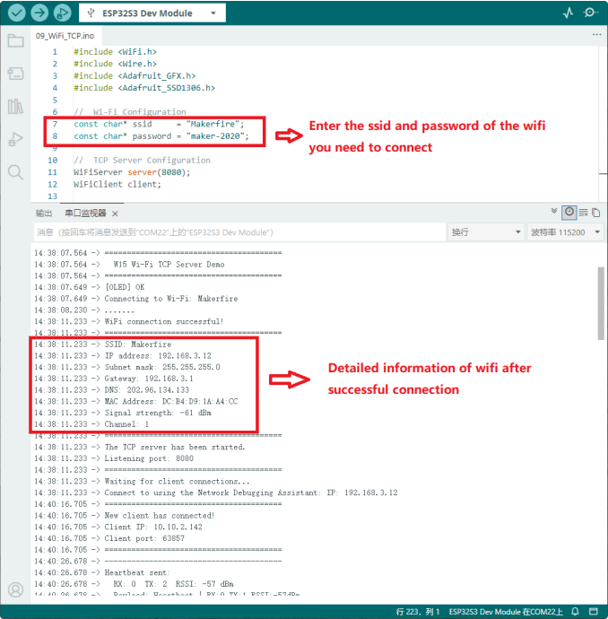
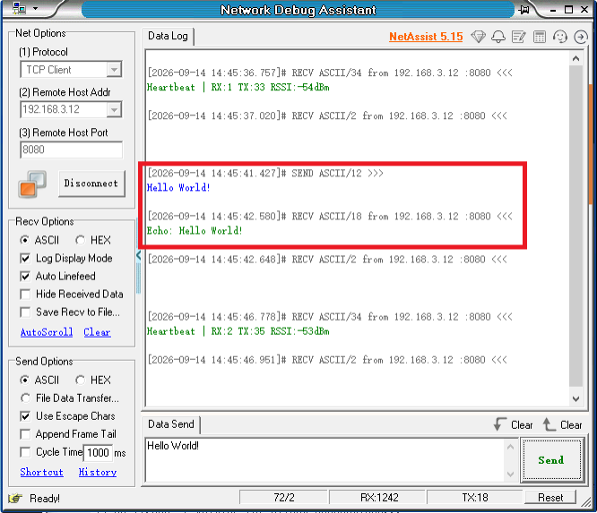
After the program runs, you can view the IP address assigned when connecting to Wi-Fi, the TCP client's IP address, and the data received on the screen.
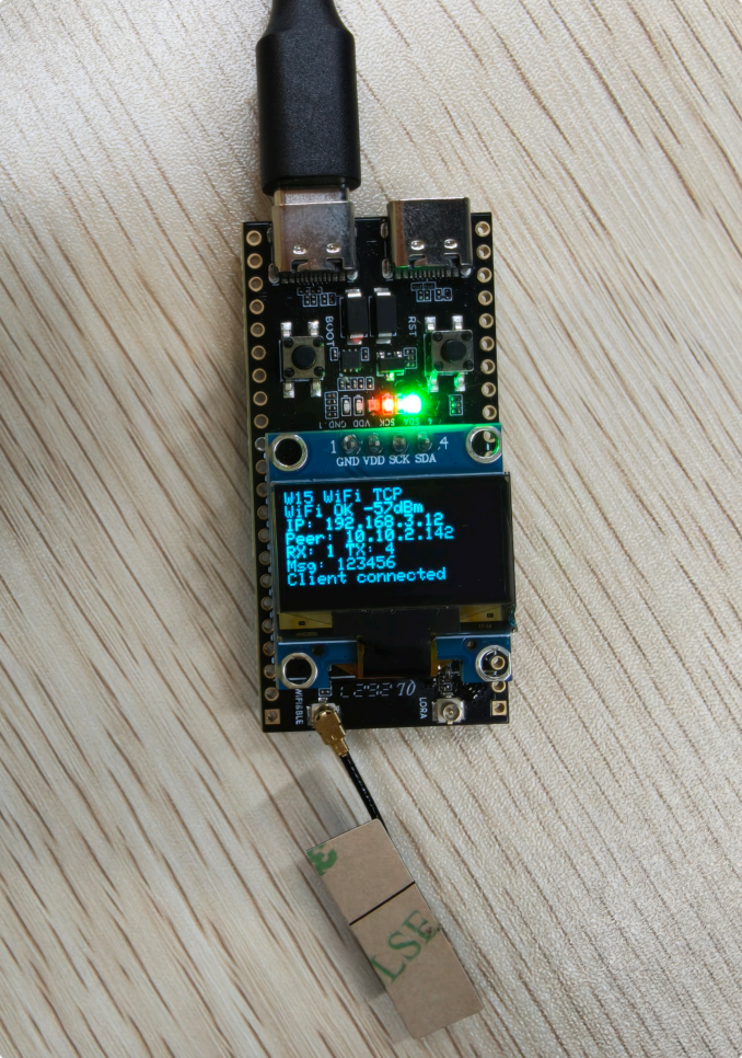
-
Real-time output of connection status, received data content, and transmitted data length
-
Displays Wi-Fi connection details and statistics
-
For easy debugging and monitoring of the program's running status
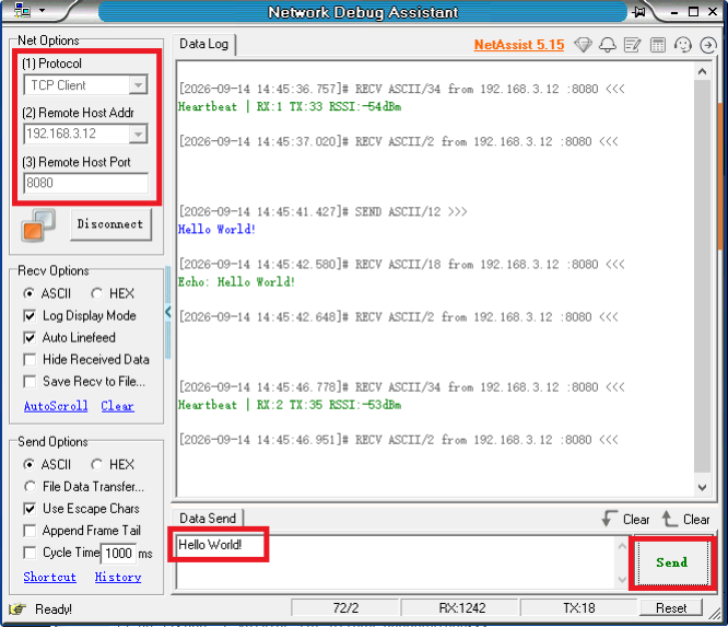
Use a TCP connection tool to establish a connection and send messages, and check whether the data is transmitted successfully
After the connection is established, the device's serial port displays a message that the client has connected.
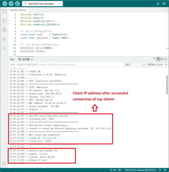
Sent successfully
10_BLE_Scan
Overview
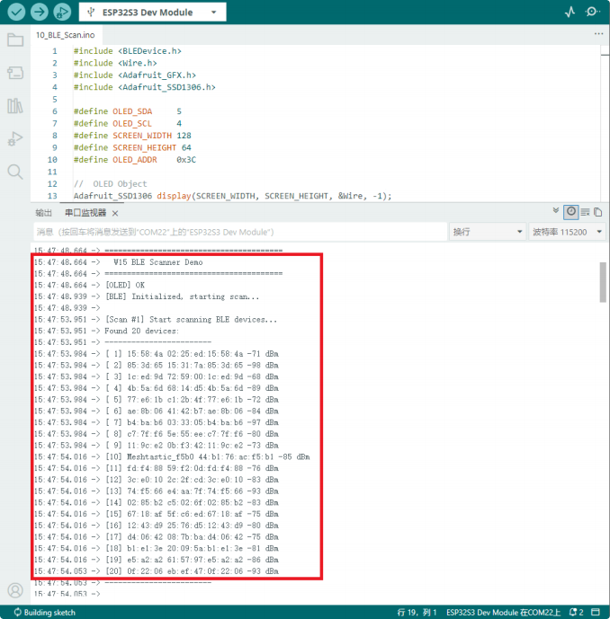
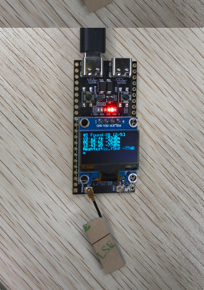
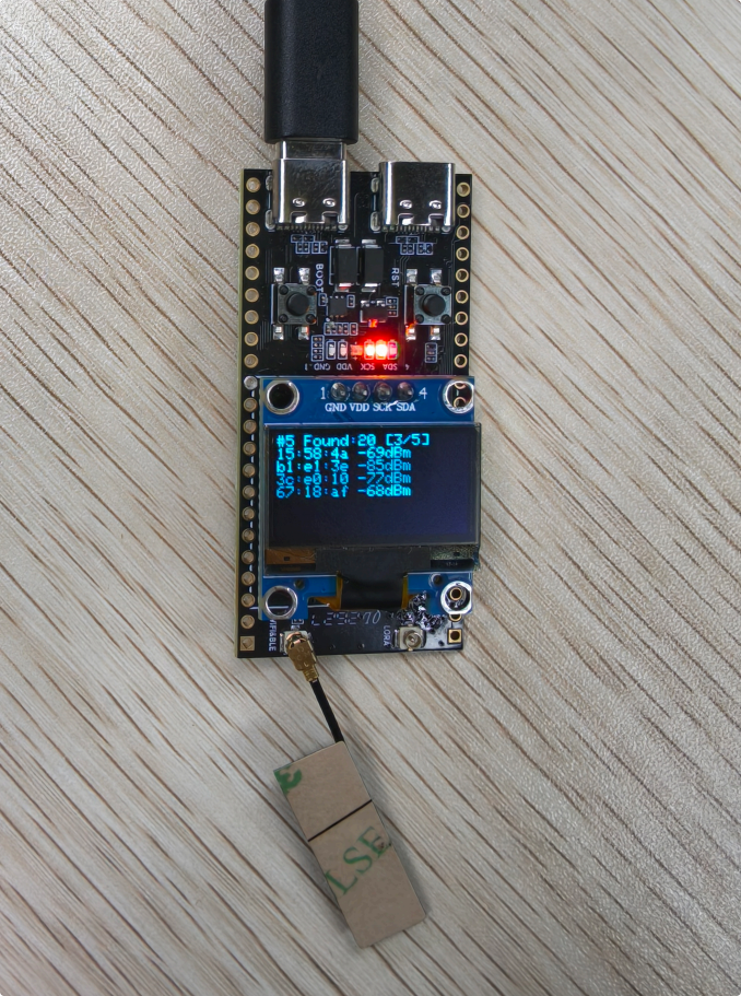
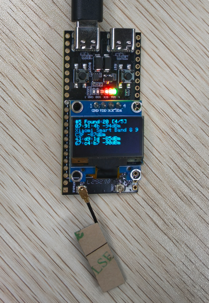
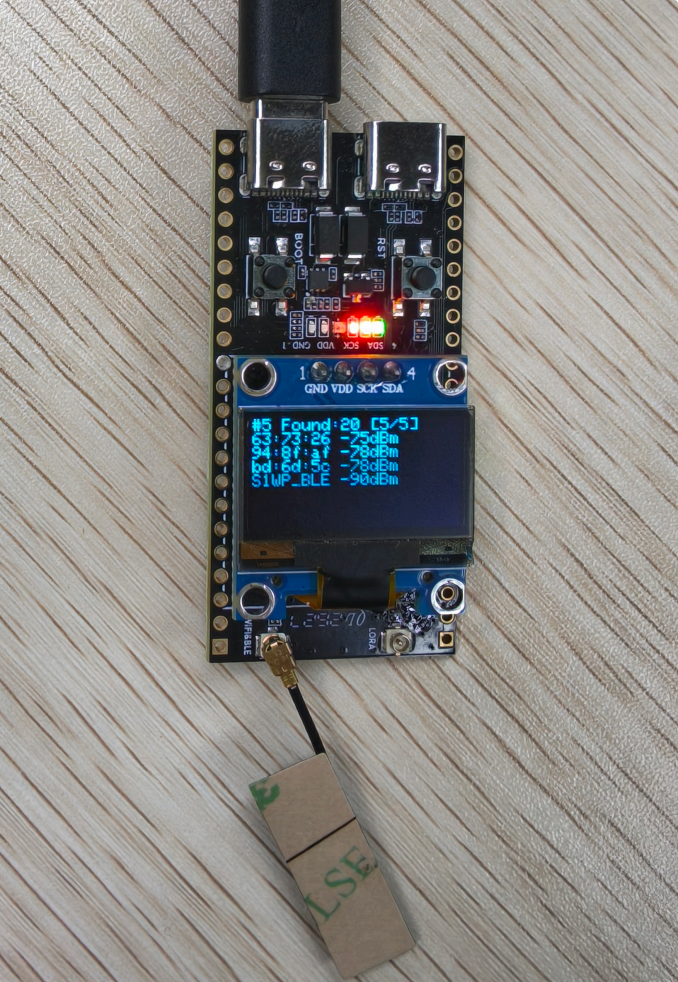
This program demonstrates the BLE Bluetooth scanning function of the W15 development board. It automatically searches for nearby Bluetooth devices and displays the device name, MAC address, and signal strength (RSSI) in real time on the OLED screen. It runs
independently without pairing with a phone.
Main features include:
-
Initializes the BLE device and enables active scanning mode; sets the duration of each scan cycle to 3 seconds
-
Automatically detects and records nearby BLE devices, caching information for up to 20 devices
-
For unnamed Bluetooth devices, the last 8 digits of the MAC address are automatically used as the device identifier
-
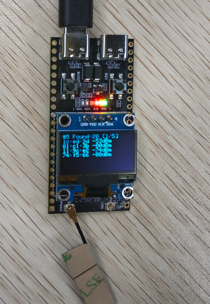
Scan results are displayed on the OLED screen in pages (four devices per page) with automatic page scrolling
-
Real-time display of scan cycle, number of detected devices, current page number, device name, and RSSI signal strength
-
The complete scan list (serial number, name, MAC, RSSI) is output via the serial port for easy debugging and viewing
-
Automatically turns on the VEXT power supply for the OLED, completing screen initialization and status refresh
-
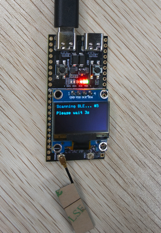
A "Please wait" prompt is displayed on the screen during scanning, improving user experience
-
After the scan completes, the results are automatically cleared and the next round begins.
Hardware connection
- Connect the board to the computer with a USB cable
Expected result
-
After power-on, the OLED display initializes and BLE scanning begins.
-
During scanning, the screen displays "Scanning"; a complete scan cycle takes 3 seconds.
-
Scan results are displayed in a paged scrolling view on the OLED screen, with four devices shown per page.
-
Displays device name and signal strength; for unidentified devices, the MAC address is displayed.
-
If no devices are found, the screen displays a prompt that no BLE devices were discovered.
-
Device information is output to the serial port, and scanning automatically restarts after each cycle completes.
11_Wi-Fi_OLED_Shape
Overview
This program demonstrates the web-based remote control function of the W15 development board over Wi-Fi. After the device connects to Wi-Fi, it starts a web server; users can then
Access the device's IP address via a web browser to remotely control the OLED display, adjust brightness, switch the RGB light on and off, and view the device's running status in real time.
Main features include:
-
Connects to the specified Wi-Fi network, starts the web server on port 80, and displays the access IP on the OLED screen.
-
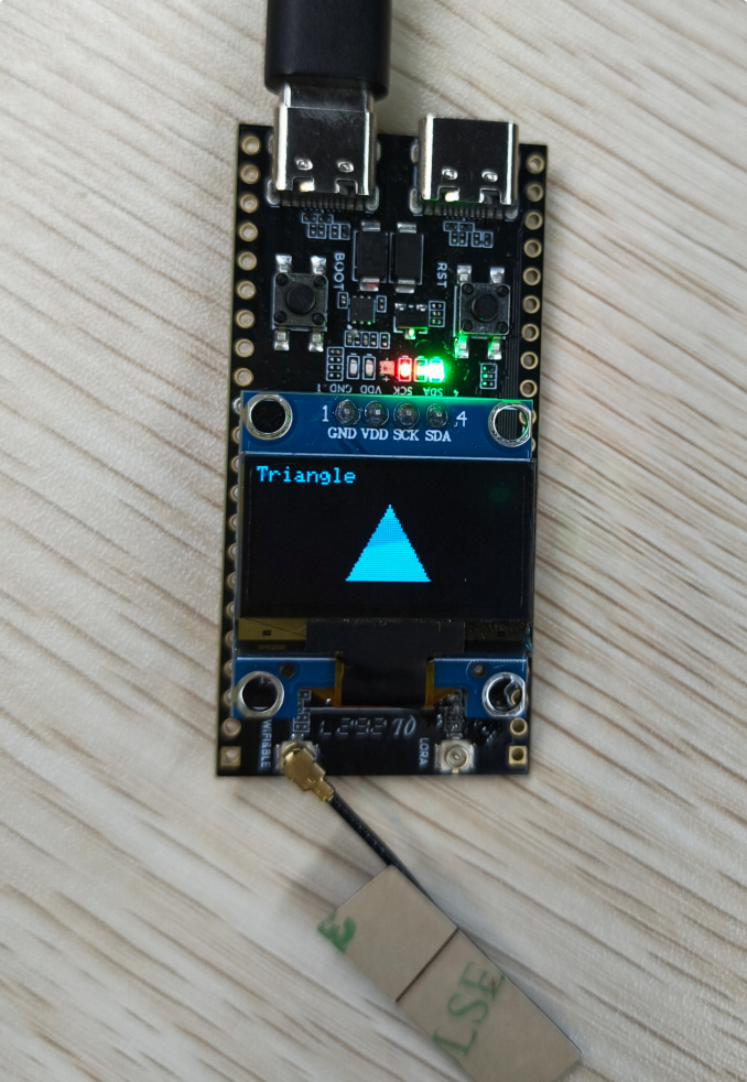
The web interface provides a graphical control panel supporting remote switching between three display shapes: square, circle, and triangle.
-
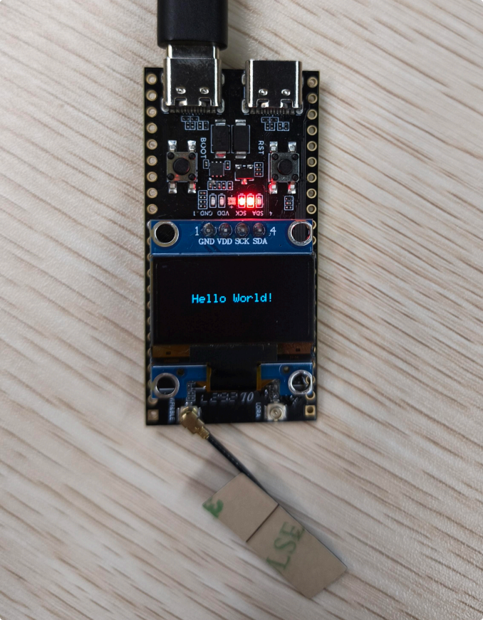
Supports custom text input via the web page, displayed in real time in the center of the OLED screen
-
Equipped with a brightness slider allowing you to adjust the OLED contrast (10–255), with changes taking effect immediately
-
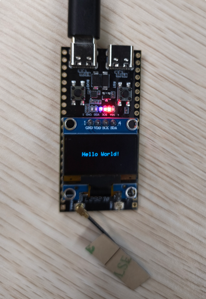
Supports remote control of the on-board green RGB LED, with the on/off status displayed synchronously on the web page
-
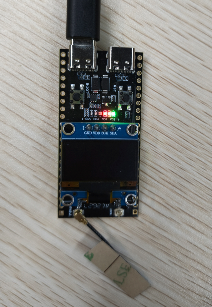
Provides a screen clear button that clears the OLED display and returns to the standby screen with a single click
-
The web page displays Wi-Fi signal strength (RSSI), device uptime, current display mode, and LED status in real time
-
Built-in automatic reconnection mechanism ensures stable and uninterrupted remote control during Wi-Fi disconnections
-
Automatically turns on the VEXT power supply for the OLED, completing screen initialization and display refresh
-
The website features a green tech design, optimized for viewing on various devices, including computers and phones.
Hardware connection
-
Connect the board to the computer with a USB cable
-
If you have confirmed the SSID and password are correct but still cannot connect via Wi-Fi, you need to attach an antenna to the Wi-Fi antenna connector on the back of the board.
Expected result
- After entering the SSID and password, the device displays the IP address once the
connection succeeds. You can then access the corresponding URL via a web browser.
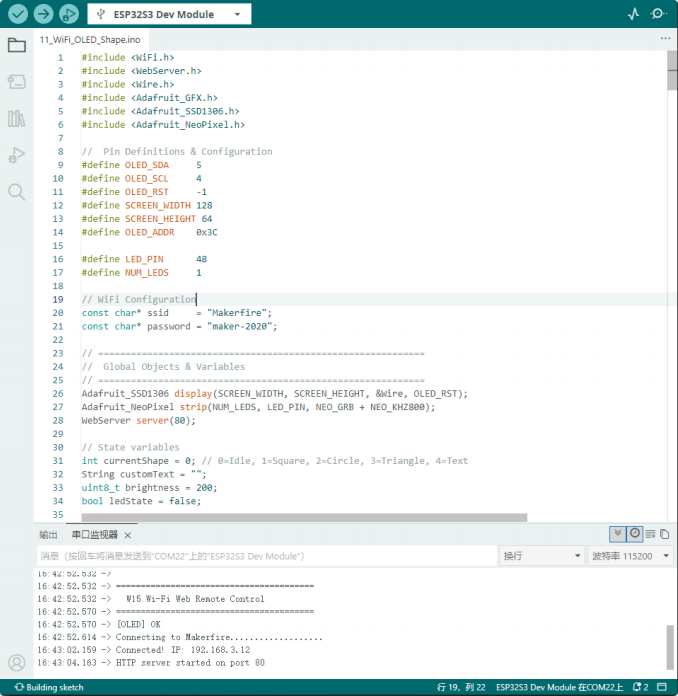
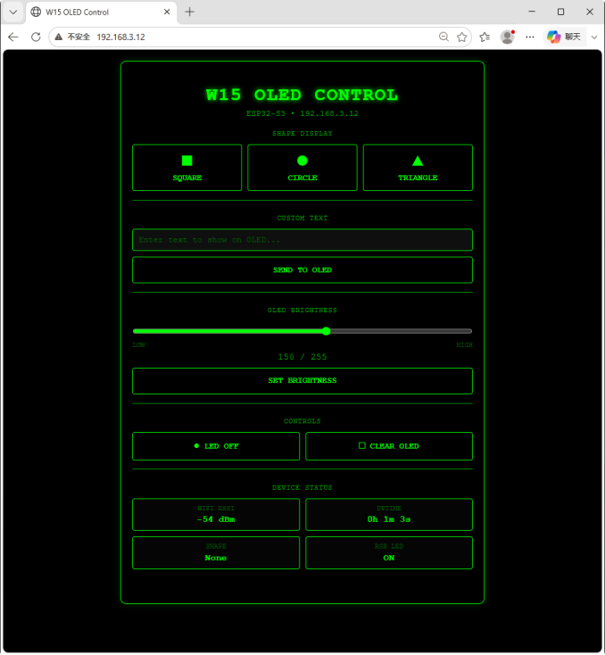
After the request succeeds, the corresponding control buttons and other elements will appear on the web page
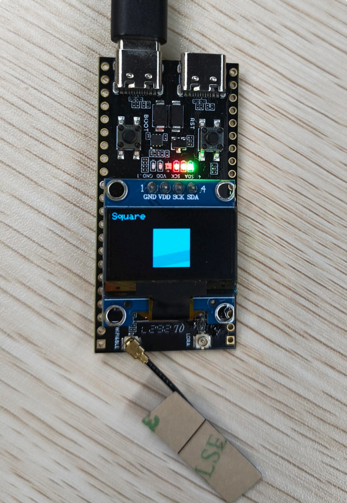
Shape display: Square
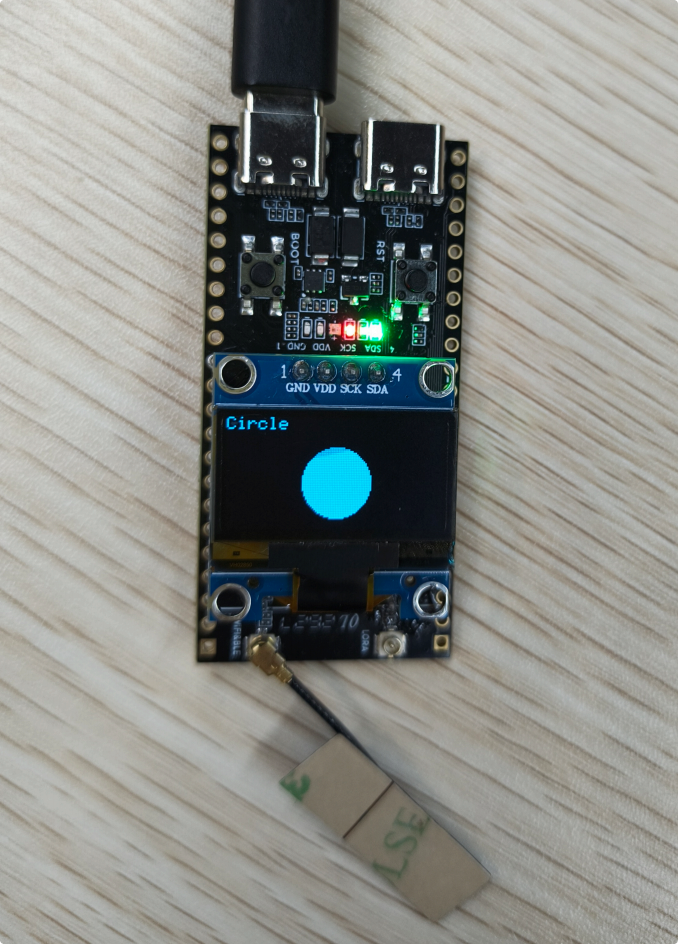
Shape display: Circle

Custom text
Control: RGB LED
Control: CLEAR OLED
Device status: The web page displays Wi-Fi signal strength (RSSI), device uptime, current display mode, and LED status in real time

12_BLE_LR2021
Overview
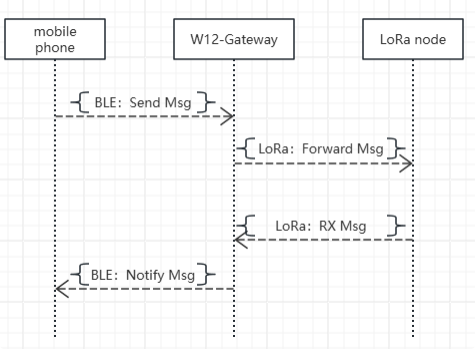
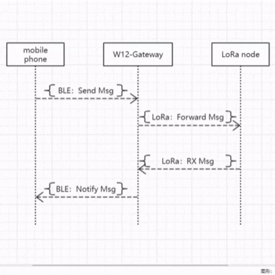
The Bluetooth + LoRa wireless gateway function of the W15 development board allows a phone to control LoRa data transmission via BLE and relay the received LoRa data back to the phone via BLE, achieving bidirectional transparent transmission and enabling wireless relaying without a network connection.
Main features include:
-
Initializes the BLE server as a device named W15-Gateway, waiting for a mobile phone to connect
-
The phone sends data via BLE; the device automatically receives it and forwards it through the LoRa module
-
Monitors LoRa wireless data in real time and automatically pushes it to your phone via BLE upon receipt
-
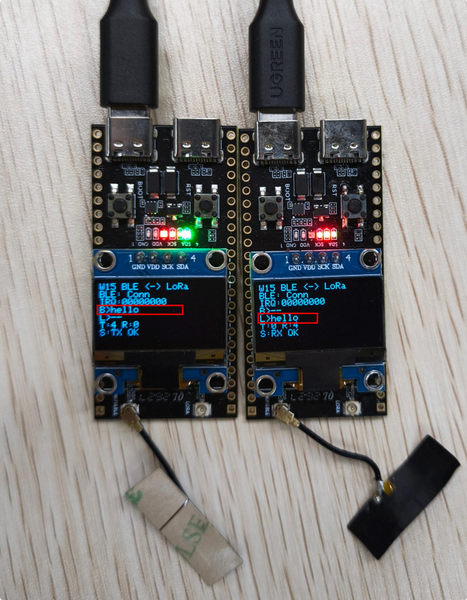
The OLED screen displays the following information in real time: BLE connection status, LoRa transmit and receive counts, the latest message, and status information
-
Built-in LoRa parameter configuration: 915 MHz frequency band, 125 kHz bandwidth, SF7, sync word 0x34
-
Synchronous serial output of BLE and LoRa transmission and reception logs for easy debugging
-
Powers the OLED, completing screen initialization and status refresh
-
Automatically restarts advertising after the BLE connection is dropped, ensuring the gateway remains available at all times
Data flow
Hardware connection
- Connect the board to the computer with a USB cable
Expected result
-
After power-on, the OLED display initializes, and the LoRa module and BLE service start automatically.
-
BLE advertises under the name W15-Gateway, waiting for a phone to connect
-
Once the phone connects via BLE, the OLED display shows "BLE connected," and the gateway enters standby mode
-
The phone sends data via BLE; the W15 receives it and transmits it via LoRa
-
Upon receiving LoRa data, the W15 automatically passes it back to the phone via BLE
-
The OLED display updates the BLE status, LoRa transmit/receive counts, and the latest message in real time
-
Synchronous serial printing of BLE and LoRa transmitted/received data and status information
-
After the BLE connection is dropped, the device automatically resumes advertising, while LoRa continues monitoring the signal
You can search for and download the nRF Connect app in the major mobile app stores; this app allows your phone to search for and connect to Bluetooth devices.
-
Android: nRF Connect
-
iOS: nRF Connect
Connect via the Bluetooth app
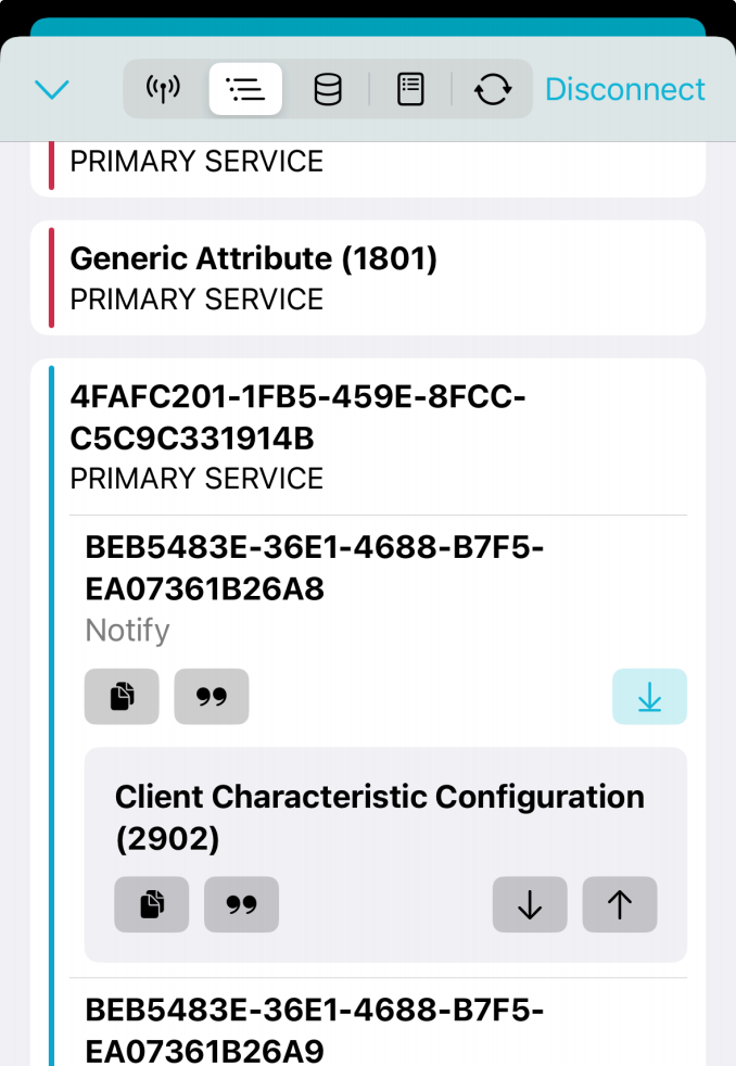
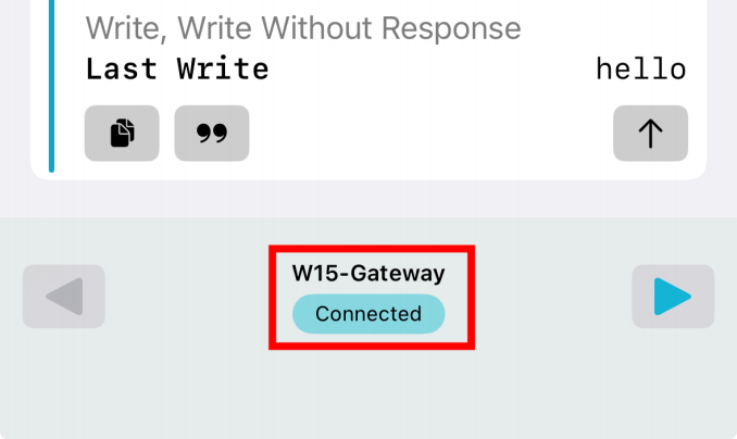
Tap this button to send data
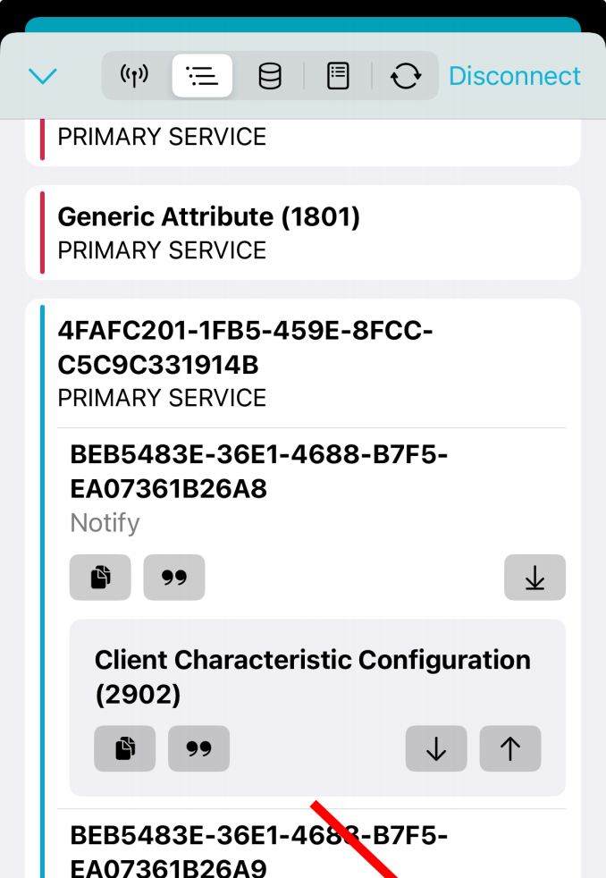
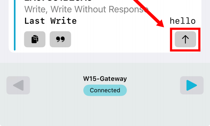
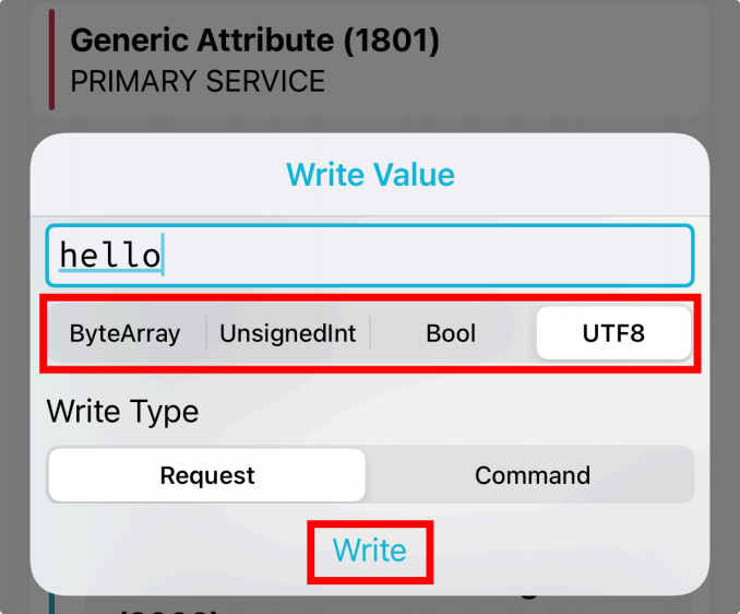
You can select the data type you want to send
Data received on the phone
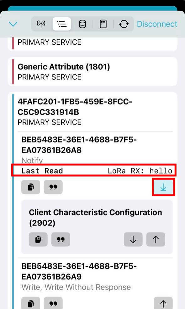
Then you can view on the device the data transmitted by the LoRa node
Resources
The source package identifies the following companion files. Add the final download links here after the files have been uploaded to the release repository:
- Arduino examples:
W15_demo - Firmware flashing utility:
flash_download_tool - Hardware files:
W15 schematicandW15 pin layout - Mechanical file:
W15 3D product model