W16 LR2021 RF Transceiver Module
Product Overview
The W16 is a compact, high-performance, multiband RF transceiver module based on the Semtech LR2021. It supports long-range LoRa communication and FLRC data rates up to 2.6 Mbps across Sub-GHz and 2.4 GHz ISM bands.
The module combines high receiver sensitivity, configurable transmit power, low-power operating modes, an SPI host interface, castellated pads, and a board-to-board connector. It is suitable for long-range IoT links, high-speed wireless data transfer, battery-powered devices, and compact embedded systems.
Typical Applications
- Industrial sensor monitoring and remote equipment status reporting
- Wireless water and gas meters
- Smart agriculture and environmental monitoring
- Smart-city infrastructure and distributed sensing
- Security, alarm, and emergency notification terminals
- Portable data loggers and battery-powered wireless terminals
- Point-to-point, star, and LoRa mesh networks
Key Features
- Multiband RF operation: Sub-GHz 868/915 MHz and 2.4 GHz ISM
- LoRa, FLRC, FSK, OOK, O-QPSK, and LR-FHSS modulation support
- Sub-GHz LoRa sensitivity down to -141.5 dBm at SF12, CR 4/5, and 125 kHz bandwidth
- Configurable Sub-GHz transmit power from -10 dBm to +22 dBm
- Typical 2.4 GHz transmit power up to +12 dBm
- FLRC data rates up to 2.6 Mbps
- LoRaWAN compatibility
- Low-power sleep mode with current consumption of 2 µA or less
- SPI host interface
- IPEX-3 antenna connectors for Sub-GHz and 2.4 GHz
- Castellated pads and DF40C board-to-board connector
- Direct connection to the W11 ESP32-S3 Mini Module
Specifications
RF Characteristics
| Parameter | Specification |
|---|---|
| RF transceiver | Semtech LR2021 |
| Frequency bands | Sub-GHz 868/915 MHz; 2.4 GHz ISM |
| Modulation | LoRa, FLRC, FSK, OOK, O-QPSK, LR-FHSS |
| LoRa data rate | 45.8 bps to 125 kbps |
| FLRC data rate | 0.13 Mbps to 2.6 Mbps |
| FSK data rate | 0.5 kbps to 2 Mbps |
| Sub-GHz transmit power | -10 dBm to +22 dBm |
| 2.4 GHz transmit power | Typically +12 dBm, configurable |
| Sub-GHz receive sensitivity | -141.5 dBm at SF12, CR 4/5, BW 125 kHz |
| 2.4 GHz receive sensitivity | -130.5 dBm at SF12, CR 4/5, BW 812 kHz |
| FLRC receive sensitivity | -111 dBm at 260 kbps |
| LoRa spreading factors | SF5 to SF12 |
Bandwidth clarification: 125 kbps is a data rate, while 125 kHz is a LoRa signal bandwidth. For the -141.5 dBm sensitivity value, the correct condition is SF12, CR 4/5, and 125 kHz bandwidth.
Electrical Characteristics
| Parameter | Specification |
|---|---|
| Operating voltage | 3.3 V nominal; 3.7 V maximum |
| Logic voltage | 3.3 V; use level translation for other logic levels |
| Sub-GHz TX current | 105 mA at +22 dBm |
| Sub-GHz RX current | 5.7 mA at LoRa SF7 and 125 kHz bandwidth |
| 2.4 GHz TX current | 23 mA at +12 dBm |
| 2.4 GHz RX current | 6.4 mA at LoRa SF7 and 125 kHz bandwidth |
| Sleep current | 2 µA or less |
Mechanical and Interface Characteristics
| Parameter | Specification |
|---|---|
| Host interface | SPI |
| Antenna connectors | IPEX-3 |
| Module connections | Castellated pads and DF40C board-to-board connector |
| Dimensions | 24.9 × 17.8 mm |
Hardware Overview
Module Dimensions and Antenna Connections
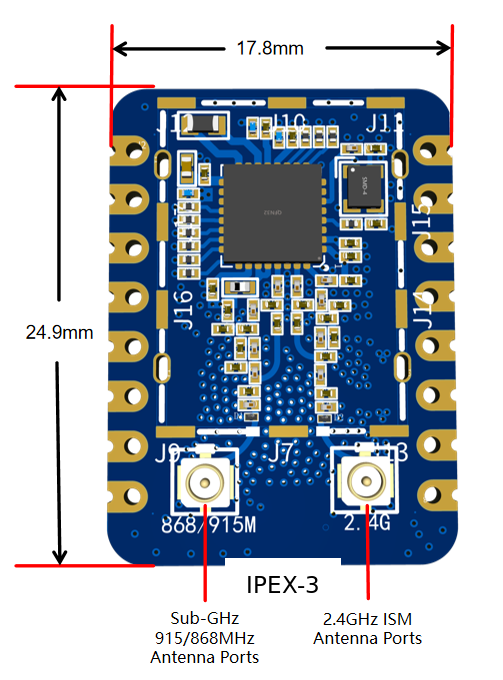
The module provides separate antenna connections for Sub-GHz 868/915 MHz and 2.4 GHz ISM operation.
Pinout
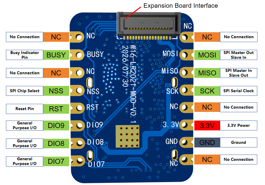
| Pin | Function | Description |
|---|---|---|
| NC | No connection | Leave unconnected |
| BUSY | Busy indicator | Indicates whether the radio is ready for a new command |
| NSS | SPI chip select | Active-low SPI chip-select input |
| RST | Reset | Hardware reset input |
| DIO7, DIO8, DIO9 | General-purpose I/O | Configurable radio digital I/O |
| MOSI | SPI data input | Host-to-module SPI data |
| MISO | SPI data output | Module-to-host SPI data |
| SCK | SPI clock | SPI serial clock |
| 3.3V | Power | 3.3 V supply |
| GND | Ground | Common ground |
Using the W16 with the W11 ESP32-S3 Mini Module
The W11 is a compact ESP32-S3 host controller that provides USB, processing, wireless connectivity, GPIO, and peripheral expansion for W16-based projects.
W11 Pinout
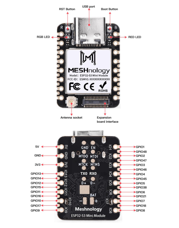
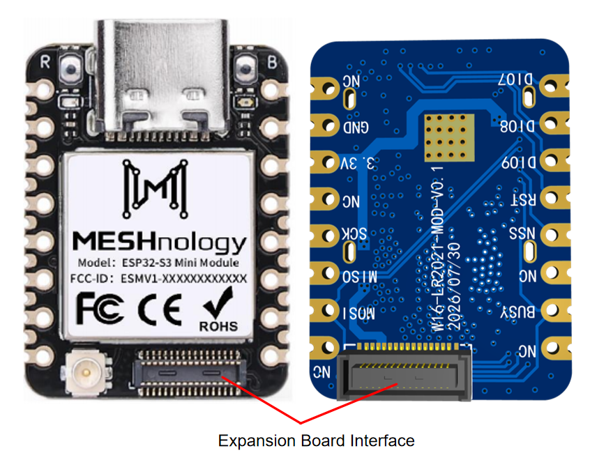
Connection Method 1 Board-to-Board Connector
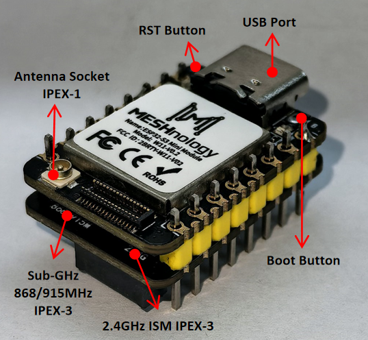
Align the W16 and W11 board-to-board connectors and press the two boards together evenly. Check connector orientation before applying pressure.
Connection Method 2 Pin Headers
The W16 and W11 can also be assembled using soldered pin headers.
Before soldering the stack, connect the antennas required for the intended Sub-GHz and 2.4 GHz configuration.
Optional Camera Expansion
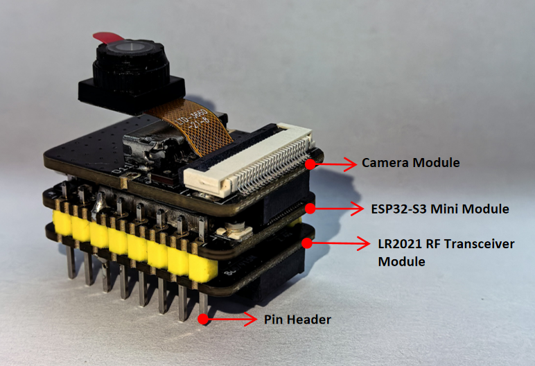
A compatible camera module can be added when the W16 and W11 are assembled using pin headers and a suitable expansion board.
Integration Notes
- Supply the module from a stable 3.3 V source and do not exceed 3.7 V.
- Use 3.3 V logic or an appropriate level translator.
- Verify the W16 and W11 connector orientation before assembly.
- Connect the correct antenna to each RF port before enabling transmission.
- Select an antenna suitable for the intended frequency band.
- Keep RF traces and antenna cables away from digital noise sources where possible.