W11(ESP32S3 Mini Module)
Product Introduction
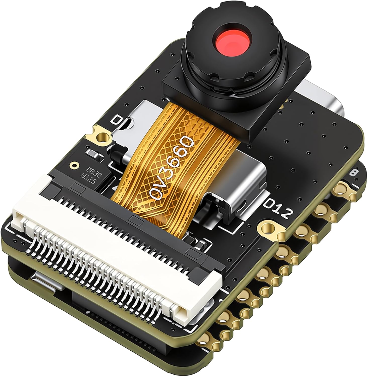
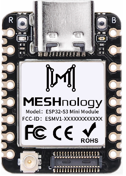
Product display image:
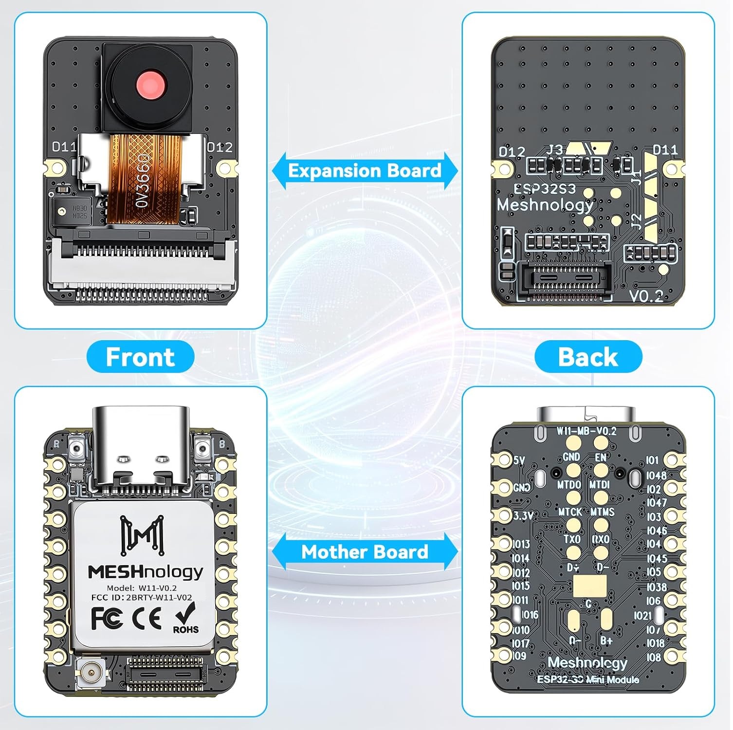
Product appearance and structural diagram:
If you’d like to view the 3D renderings, please click the link.
Product Features
The ESP32S3 Mini Module Pro series development board boasts an ultra-compact hardware form factor. Featuring a unified, streamlined hardware architecture, it achieves a genuinely "thumb-sized" design for maximum portability. Whether carried for on-the-go project debugging or embedded within miniature devices, it adapts effortlessly to any scenario.
Within its compact footprint, this development board integrates a wealth of hardware. Beyond the core ESP32-S3 chip, it incorporates a camera sensor and digital microphone, with native support for microSD card expansion. The camera sensor captures high-definition images and short videos, while the digital microphone precisely captures ambient audio signals. The SD card provides a stable local storage solution for collected audio-visual data and AI model files.
Notably, the embedded machine learning capabilities of the ESP32-S3 chip synergise perfectly with the board's audio-visual capture hardware. Developers can directly undertake intelligent image recognition, voice wake-up and recognition, and edge AI inference tasks without requiring complex external modules. Indeed, the ESP32S3 Mini Module series represents the ideal choice for makers, electronics engineers, and AI beginners embarking on intelligent voice and visual AI projects.
Technical Specifications
Specifications
| Category | Parameter Item | Specification Requirements |
|---|---|---|
| Core processor | Chip model | ESP32-S3 (dual-core 32-bit LX7 microprocessor) |
| Primary frequency | Up to 240MHz | |
| Built-in SRAM | 512KB | |
| Built-in PSRAM | 8MB (supports high-resolution image caching and multi-task data storage) | |
| Distinctive Features | Hardware floating-point operations, vector instruction set, neural network accelerator (NPU, supporting INT8/FP16 precision AI inference) | |
| Storage Configuration | On-board Flash | 8/16MB SPI NOR Flash (supporting OTA firmware upgrades and firmware encryption) |
| Extended storage support | SPI interface expansion, compatible with SD cards up to 128GB | |
| Wireless connectivity | Wi-Fi Standard / Frequency Band | 802.11b/g/n, 2.4GHz band |
| Wi-Fi transmission rate / distance | Maximum 150Mbps, indoor range ≥50m, open terrain range ≥100m (packet loss rate ≤1% at 100m) | |
| Wi-Fi Mode / Security Protocol | Station/SoftAP/ Hybrid Mode; Supports WPA3/WPA2-PSK | |
| Bluetooth version / mode | Bluetooth 5.0, supporting BLE low-energy mode, traditional Bluetooth mode, and Bluetooth Mesh networking | |
| Bluetooth transmission rate / range | Maximum 2Mbps, BLE indoor range 32m, long-range mode in open terrain ≥1km | |
| Input/output interface | Number of GPIO pins | Up to 32 reusable GPIOs (all supporting interrupt triggering: rising edge / falling edge / both edges) |
| ADC channel | 20-channel 12-bit precision, input range 0–3.3V | |
| SPI interface | 3 channels (1 high-speed SPI at 40MHz for PSRAM/Flash, 2 general-purpose SPI for peripheral expansion) | |
| UART interface | 2-wire, supporting 1MHz high-speed mode | |
| UART interface | 3-channel, maximum baud rate 2Mbps (supports hardware flow control) | |
| Other key interfaces | 2-channel I²S (audio input/output), 2-channel DAC (8-bit precision), 8-channel PWM, 1-channel USB Type-C (data/power supply/programming) | |
| Additional Function Interface | Lithium battery interface (3.7V), user button (reset / customisable), RGB LED (status indicator) | |
| Sensor configuration | On-board sensors (standard equipment) | 1. Temperature sensor: Accuracy ±0.1°C, measurement range -40°C to 125°C 2. Inertial sensor: Accelerometer range ±2g to 16g, gyroscope ±16°/s to ±2048°/s (selectable) |
| External sensor support | Sensors compatible with I2C/SPI/ADC interfaces, including temperature and humidity, light, gas, distance, and gyroscope sensors (supporting sensor wake-up functionality) | |
| Power Management | Power supply method | 1. USB Type-C (5V/1A) 2. Lithium battery (3.7V, 300mAh–2000mAh) 3. External DC (3.3V–5V/1A peak) |
| Charging Management | Adjustable charging current (maximum 1A) with LED charging status indicator; features overcharge/over-discharge/overcurrent/short-circuit protection. | |
| Power consumption (typical value) | Active mode ≤ 120mA; Light sleep ≤ 15mA; Deep sleep ≤ 8µA; Sleep mode ≤ 1µA | |
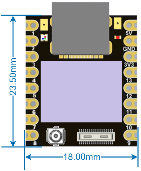
| Physical and Environmental Characteristics | Dimensions | 24.54mm × 17.78mm × 4.50mm |
| Weight | 2.44g(Single ESP32-S3 module) | |
| Physical and Environmental Characteristics | PCB Specifications | 1.6mm thick FR-4 laminate, immersion gold plating process |
| Operating temperature range | -40℃~85℃(Industrial grade) | |
| Storage temperature range | -55℃~125℃ | |
| Operating humidity | 5%~95% RH(non-condensing) | |
| Reliability | Mean Time Between Failures (MTBF) | ≥20,000 hours |
| Electromagnetic Compatibility (EMC) | Complies with CE EN 300 328 and FCC Part 15B standards | |
| Electrostatic Discharge (ESD) Protection | Contact discharge ±8kV, air discharge ±15kV (IEC 61000-4-2 standard) | |
| IO Output Current Limiting | Single pin ≤ 20mA, total IO current ≤ 100mA | |
| Vibration-resistant / Shock-resistant | Vibration resistance: 10–2000 Hz, 10g acceleration (IEC 60068-2-6); Shock resistance: 1000g, 0.5ms half-sine wave (IEC 60068-2-27) |
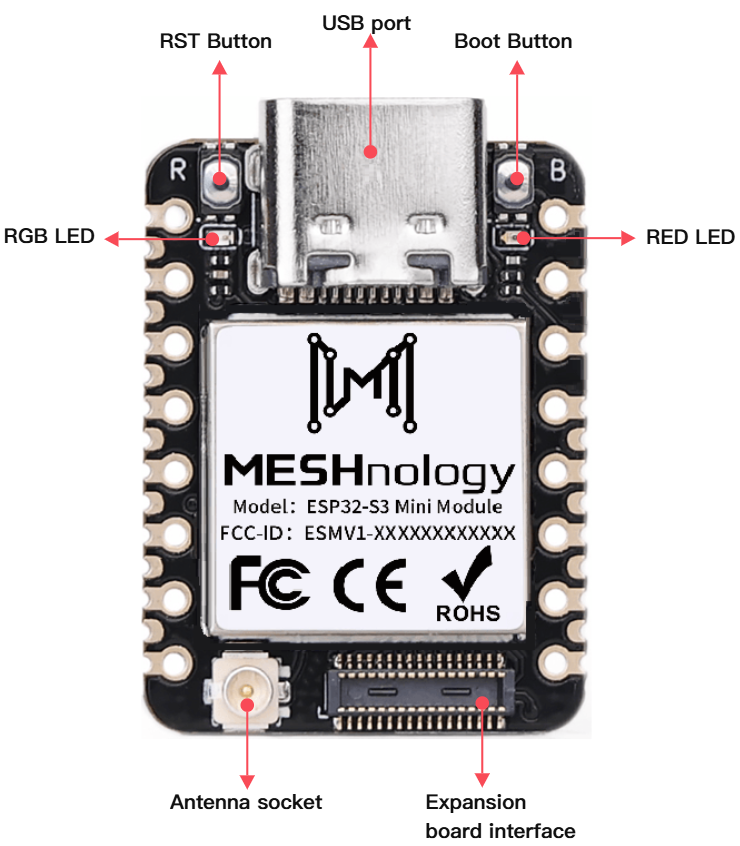
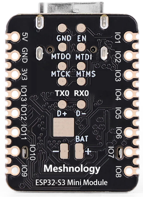
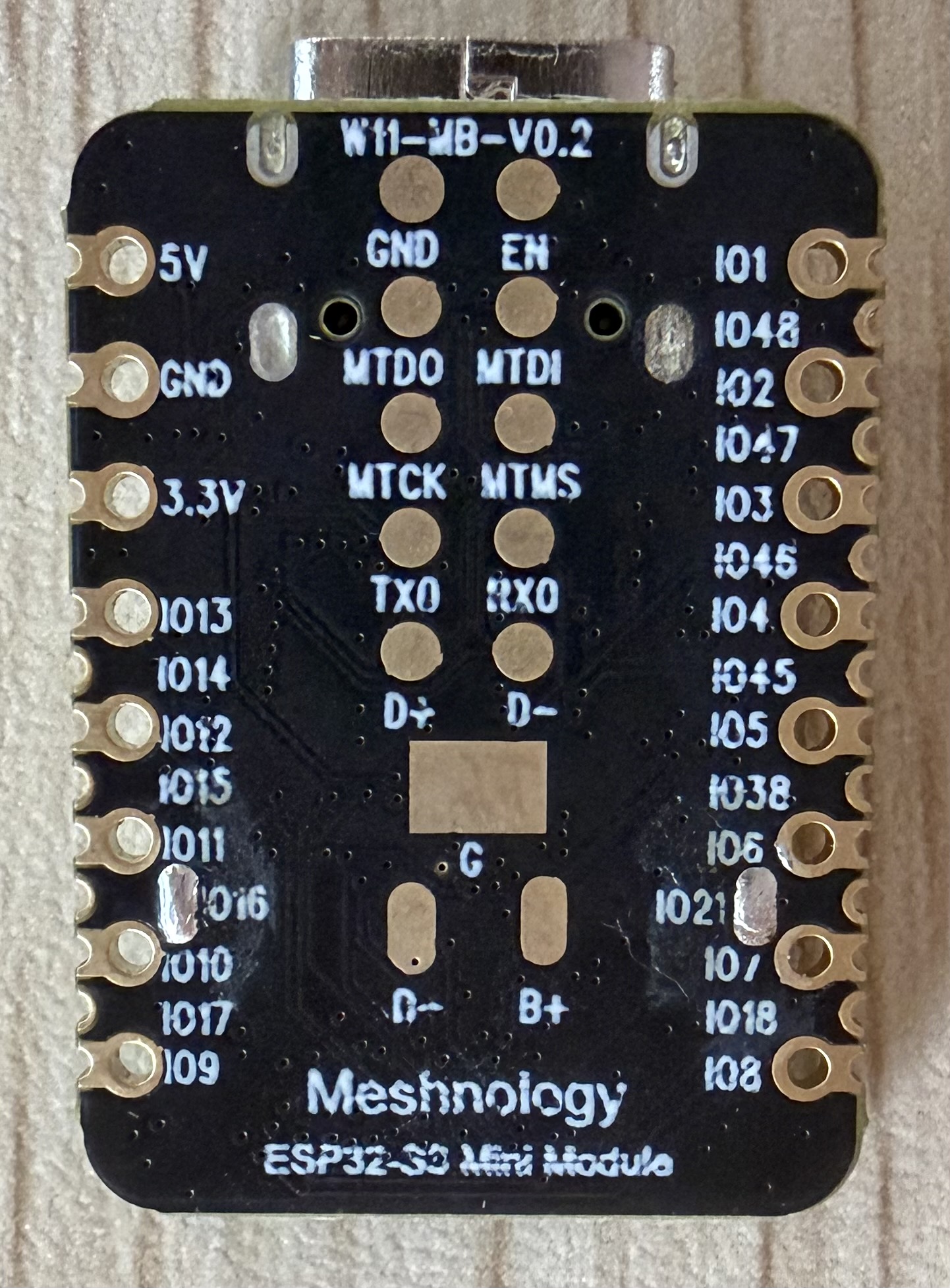
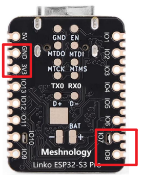
Hardware pin
 |  |
|---|
Module front:
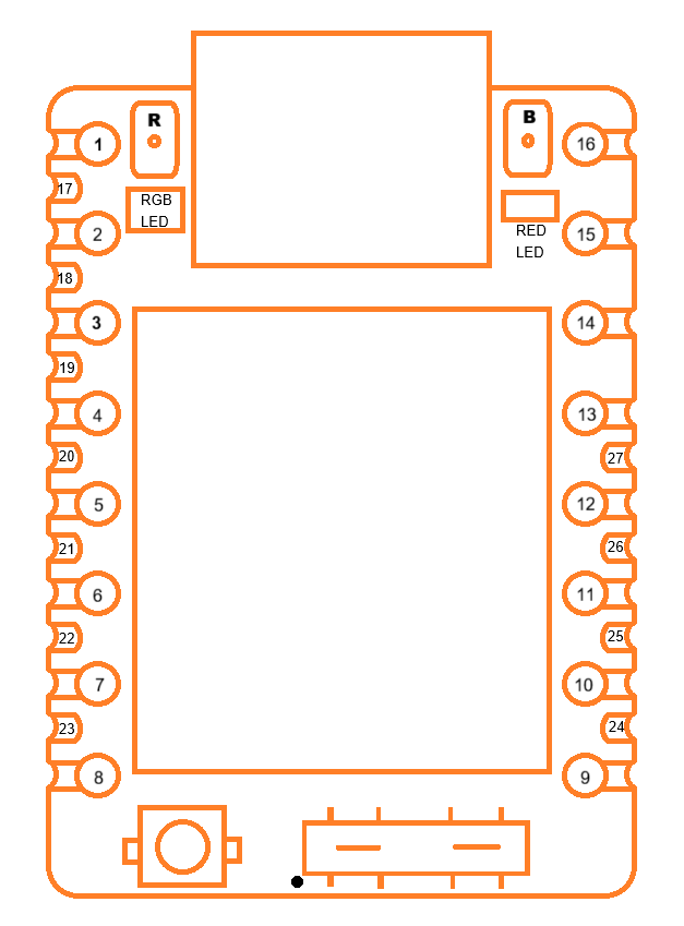
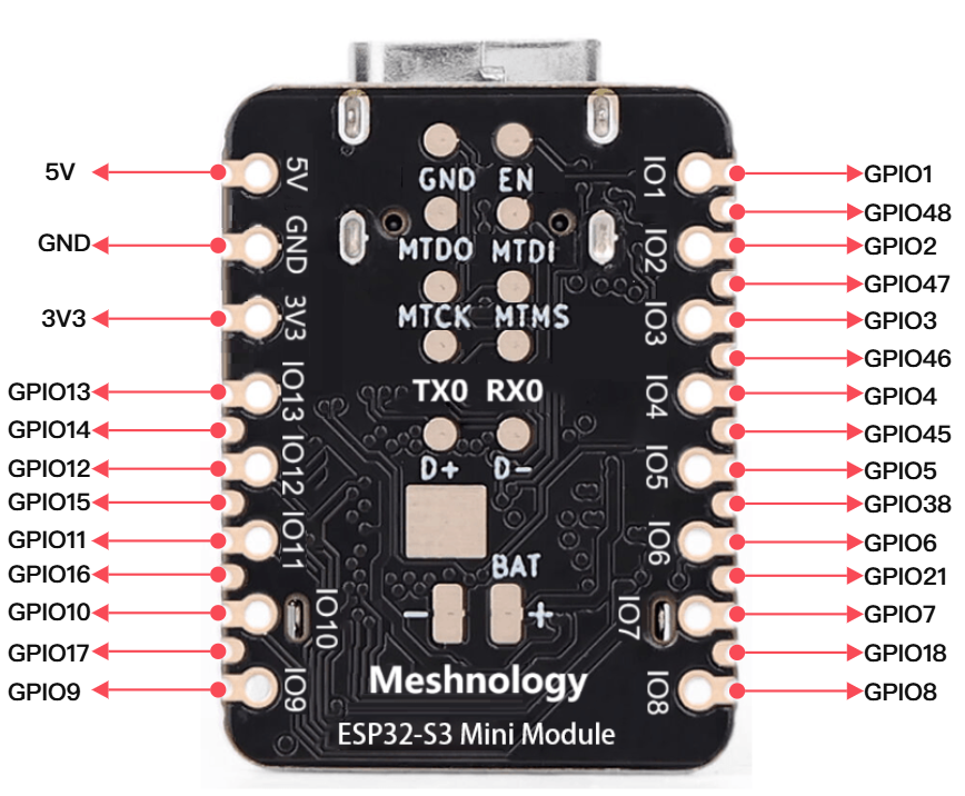
1、Pin holes on the left side of the module, from top to bottom
| No. | Name | Type | Function |
|---|---|---|---|
| 1 | IO1 | I/O | GPIO1, ADC, UART, PWM, I2S, I2C, SPI |
| 2 | IO2 | I/O | GPIO2, ADC, UART, PWM, I2S, I2C, SPI |
| 3 | IO3 | I/O | GPIO3, ADC, UART, PWM, I2S, I2C, SPI |
| 4 | IO4 | I/O | GPIO4, ADC, UART, PWM, I2S, I2C, SPI |
| 5 | IO5 | I/O | GPIO5, ADC, UART, PWM, I2S, I2C, SPI |
| 6 | IO6 | I/O | GPIO6, ADC, UART, PWM, I2S, I2C, SPI |
| 7 | IO7 | I/O | GPIO7, ADC, UART, PWM, I2S, I2C, SPI |
| 8 | IO8 | I/O | GPIO8, ADC, UART, PWM, I2S, I2C, SPI |
2、Pin holes on the right side of the module, from top to bottom
| No. | Name | Type | Function |
|---|---|---|---|
| 16 | 5V | P | Power input or output 5.0V |
| 15 | GND | G | Ground |
| 14 | 3V3 | P | Output 3.3V, power supply for external sensor |
| 13 | IO13 | I/O | GPIO13, ADC, UART, PWM, I2S, I2C, SPI |
| 12 | IO12 | I/O | GPIO12, ADC, UART, PWM, I2S, I2C, SPI |
| 11 | IO11 | I/O | GPIO11, ADC, UART, PWM, I2S, I2C, SPI |
| 10 | IO10 | I/O | GPIO10, ADC, UART, PWM, I2S, I2C, SPI |
| 9 | IO9 | I/O | GPIO9, ADC, UART, PWM, I2S, I2C, SPI |
3、SMA stamp holes on the left side of the module, from top to bottom
| No. | Name | Type | Function |
|---|---|---|---|
| 17 | IO48 | I/O | GPIO48, UART, PWM, I2S, I2C, SPI |
| 18 | IO47 | I/O | GPIO47, UART, PWM, I2S, I2C, SPI |
| 19 | IO46 | I/O | GPIO46, UART, PWM, I2S, I2C, SPI |
| 20 | IO45 | I/O | GPIO45, UART, PWM, I2S, I2C, SPI |
| 21 | IO38 | I/O | GPIO38, UART, PWM, I2S, I2C, SPI |
| 22 | IO21 | I/O | GPIO21, UART, PWM, I2S, I2C, SPI |
| 23 | IO18 | I/O | GPIO18, ADC, UART, PWM, I2S, I2C, SPI |
4、SMA stamp holes on the right side of the module, from top to bottom
| No. | Name | Type | Function |
|---|---|---|---|
| 27 | IO14 | I/O | GPIO14, ADC, UART, PWM, I2S, I2C, SPI |
| 26 | IO15 | I/O | GPIO15, ADC, UART, PWM, I2S, I2C, SPI |
| 25 | IO16 | I/O | GPIO16, ADC, UART, PWM, I2S, I2C, SPI |
| 24 | IO17 | I/O | GPIO17, ADC, UART, PWM, I2S, I2C, SPI |
5、DF40C-30Pin module socket, from the lower left pin to the upper left corner
| No. | Name | Type | Function |
|---|---|---|---|
| 1 | NC | / | Reserved |
| 2 | IO3 | I/O | GPIO3, ADC, UART, PWM, I2S, I2C, SPI |
| 3 | IO7 | I/O | GPIO7, ADC, UART, PWM, I2S, I2C, SPI |
| 4 | IO8 | I/O | GPIO8, ADC, UART, PWM, I2S, I2C, SPI |
| 5 | IO9 | I/O | GPIO9, ADC, UART, PWM, I2S, I2C, SPI |
| 6 | IO10 | I/O | GPIO10, ADC, UART, PWM, I2S, I2C, SPI |
| 7 | IO11 | I/O | GPIO11, ADC, UART, PWM, I2S, I2C, SPI |
| 8 | IO12 | I/O | GPIO12, ADC, UART, PWM, I2S, I2C, SPI |
| 9 | IO13 | I/O | GPIO13, ADC, UART, PWM, I2S, I2C, SPI |
| 10 | IO14 | I/O | GPIO14, ADC, UART, PWM, I2S, I2C, SPI |
| 11 | IO15 | I/O | GPIO15, ADC, UART, PWM, I2S, I2C, SPI |
| 12 | IO16 | I/O | GPIO16, ADC, UART, PWM, I2S, I2C, SPI |
| 13 | IO17 | I/O | GPIO17, ADC, UART, PWM, I2S, I2C, SPI |
| 14 | IO18 | I/O | GPIO18, ADC, UART, PWM, I2S, I2C, SPI |
| 15 | VIN | P | Power input for module, Voltage range is 3.7~5.0V |
| 16 | IO21 | I/O | GPIO21, UART, PWM, I2S, I2C, SPI |
| 17 | GND | G | Ground |
| 18 | 3V3 | P | Output 3.3V, power supply for external sensor |
| 19 | 3V3 | P | Output 3.3V, power supply for external sensor |
| 20 | NC | / | Reserved |
| 21 | IO48 | I/O | GPIO48, UART, PWM, I2S, I2C, SPI |
| 22 | IO47 | I/O | GPIO47, UART, PWM, I2S, I2C, SPI |
| 23 | IO38 | I/O | GPIO38, UART, PWM, I2S, I2C, SPI |
| 24 | IO39 | I/O | GPIO39, UART, PWM, I2S, I2C, SPI |
| 25 | IO40 | I/O | GPIO40, UART, PWM, I2S, I2C, SPI |
| 26 | IO41 | I/O | GPIO41, UART, PWM, I2S, I2C, SPI |
| 27 | IO42 | I/O | GPIO42, UART, PWM, I2S, I2C, SPI |
| 28 | GND | G | Ground |
| 29 | GND | G | Ground |
| 30 | VIN | P | Power input for module, Voltage range is 3.7~5.0V |
DF40C-30-Pin Socket Interface Diagram
Module rear:
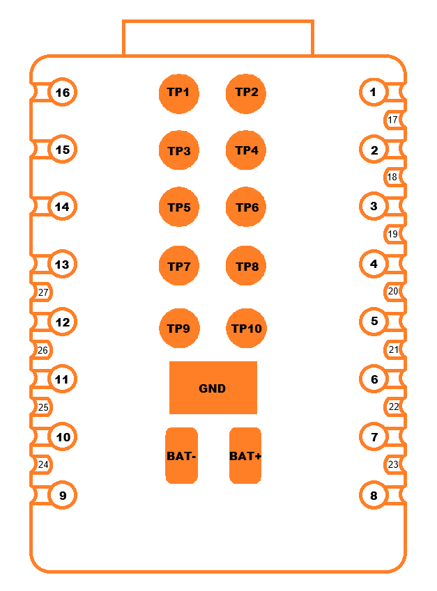
1、TP pads in the middle of the module, from top to bottom
| No. | Name | Type | Function |
|---|---|---|---|
| TP1 | GND | I/O | Ground |
| TP2 | EN | I/O | CHIP_PU, Connect to RST switch |
| TP3 | MTDO | I/O | MTDO, GPIO40, UART, PWM, I2S, I2C, SPI |
| TP4 | MTDI | I/O | MTDI, GPIO41, UART, PWM, I2S, I2C, SPI |
| TP5 | MTCK | I/O | MTCK, GPIO39, UART, PWM, I2S, I2C, SPI |
| TP6 | MTMS | I/O | MTMS, GPIO42, UART, PWM, I2S, I2C, SPI |
| TP7 | TX0 | I/O | U0TXD, GPIO43, UART, PWM, I2S, I2C, SPI |
| TP8 | RX0 | I/O | U0RXD, GPIO44, UART, PWM, I2S, I2C, SPI |
| TP9 | D+ | I/O | USB_D+, GPIO20, ADC, UART, PWM, I2S, I2C, SPI |
| TP10 | D- | I/O | USB_D-, GPIO19, ADC, UART, PWM, I2S, I2C, SPI |
| GND | GND | G | Ground |
| BAT- | BAT- | P | Input 3.7~4.2V, Battery negative terminal input |
| BAT+ | BAT+ | P | Input 3.7~4.2V, Battery positive terminal input |
Product dimensions
Dimension Drawing:
Instructions for Use
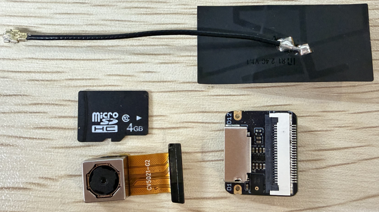
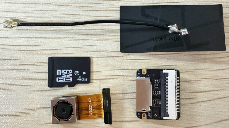
Hardware Preparation
- ESP32S3 Mini Module Mainboard + Expansion Board
- SD Card + OV5640 Camera + Antenna
- Supplementary: USB Cable (Type A Male to Type C Male) x1, Card Reader
 |  |
|---|
Software Preparation
- Arduino IDE、flash_download_tool
Arduino development
Environment Setup
Downloading and Installing the Arduino IDE
Arduino download website:arduino.cc/en/software
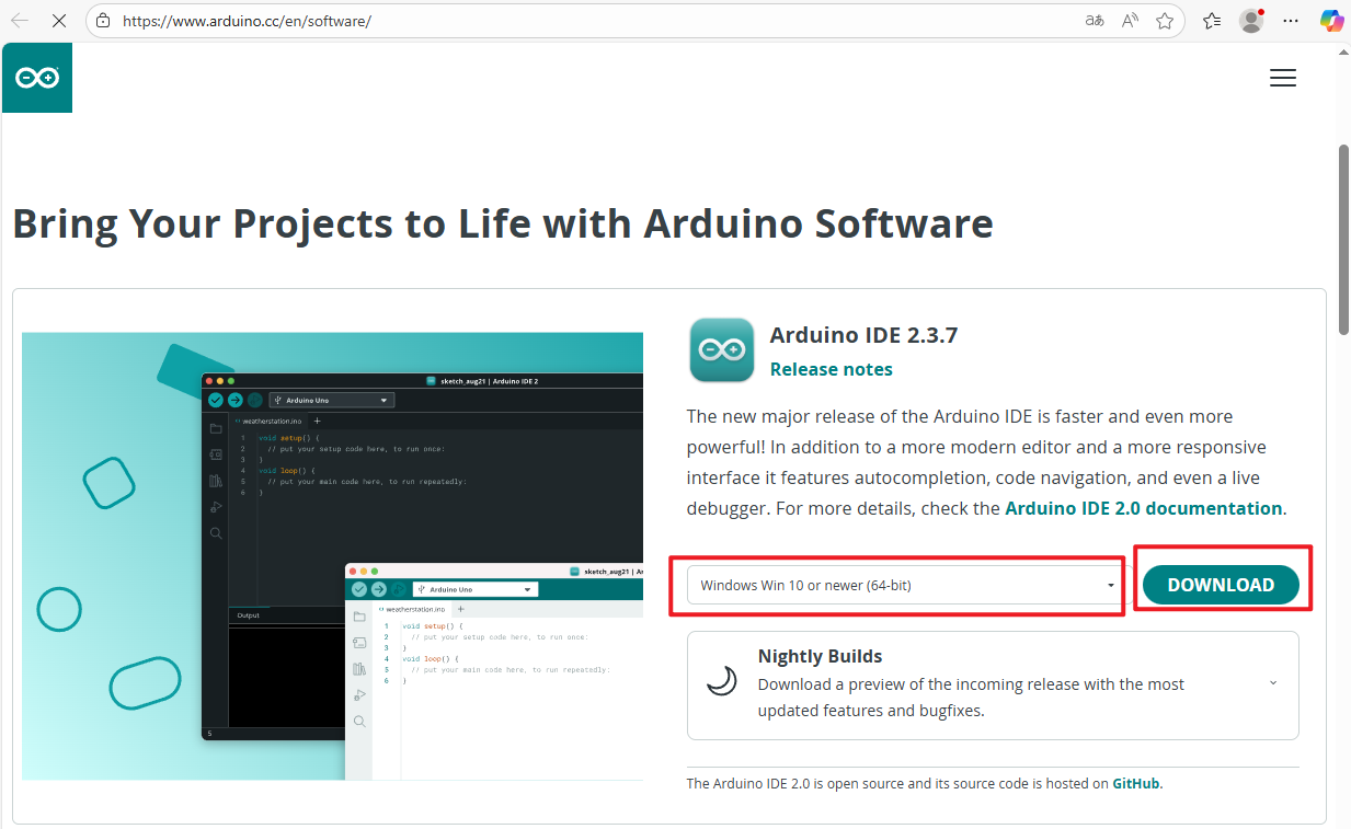
Follow the installation instructions provided with the Arduino software to download and install.
Installing the ESP32 Development Board
- To use ESP32-related boards within the Arduino IDE, you must first install the "esp32 by Espressif Systems" development board package.
- Proceed with installation according to the board installation requirements.
After opening the software:
File - Preferences
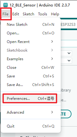 Add the address of the development board manager
-
Stable release link:
https://espressif.github.io/arduino-esp32/package_esp32_index.json
-
Development version link:
https://espressif.github.io/arduino-esp32/package_esp32_dev_index.json
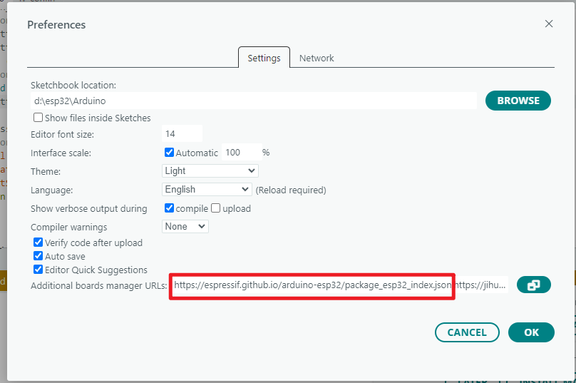 Once completed, select OK
Installing the development board
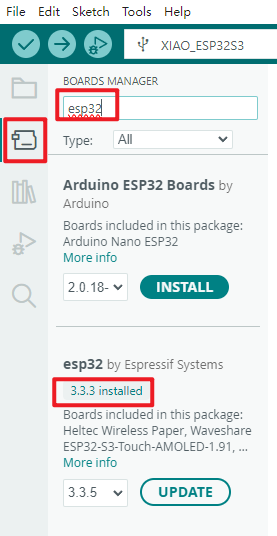
- Select the Board Manager from the left-hand side of the software
- Search for esp32 in the search bar
- From the found boards, select a version ≥3.2.0 for esp32 by Espressif Systems
- Click Install
- Upon clicking, a similar prompt message will appear in the bottom-right corner of the software. Please wait for the download to complete (ensure a stable internet connection during the download).
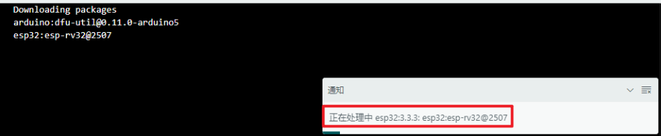
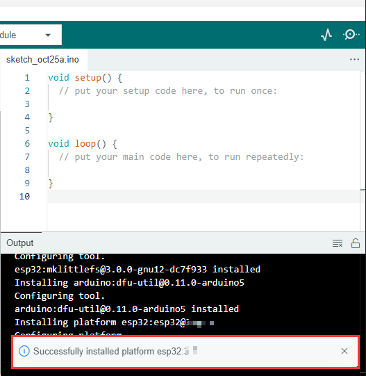
- Upon completion of the download, a success notification will appear.
- When searching again, the term 'already installed' will appear.
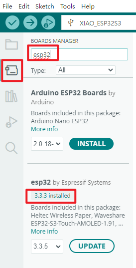
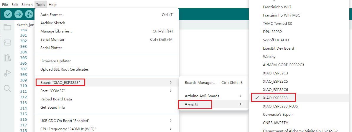
The development board type for this product is XIAO_ESP32S3.
Before each programming session, it is essential to verify that the development board type is correct.
Required libraries for installation
When installing Arduino libraries, there are typically two methods available: online installation and offline installation. Should a library require offline installation, the provided library files must be used. For most libraries, users can easily search for and install them via the Arduino software's online library manager. However, some open-source or custom libraries are not synchronised with the Arduino Library Manager and thus cannot be obtained via online search. In such cases, users must manually install these libraries offline.
The W11 (ESP32S3 Mini Module) library files are stored within the example programme. Click here to proceed: (Example download link to be added)
Library files required for W11:
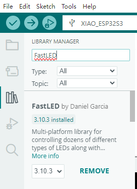
FastLED
- To illuminate the CHANGE LED
- Simply install the latest version
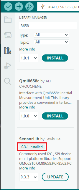
SensorLib
- Used to retrieve data from the QMI8658C sensor
- Download version
0.3.1as shown in the diagram
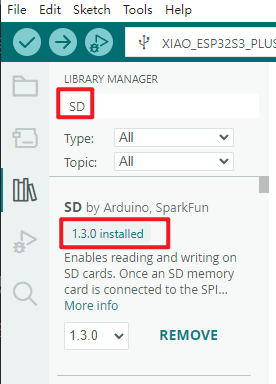
SD
- Supports SD card read and write operations
- After connecting the SD memory card to the Arduino board's SPI interface, you may create files and perform read/write operations
- You may also browse the directory structure within the SD card
- Download the
1.3.0version shown in the image
Sample Programme
All example programmes have separate .ino files, which can be modified from the source code to achieve your desired programme functionality. Pre-compiled .bin files are also provided, which can be directly flashed using the flash_download_tool utility.
Firmware programming
flash_download_tool
Download the Flash Download Tool Official download link:https://dl.espressif.com/public/flash_download_tool.zip
Download sample
This section primarily uses the ESP32-S3 series as an example to demonstrate how to perform standard programming and encrypted programming.
Standard programming
-
Pull the GPIO0 pin low to place the device into download mode.
-
Open the download tool, select
ESP32forChipType, chooseDevelopforWorkMode, and opt forUARTunderLoadMode. ClickOKas illustrated below.

-
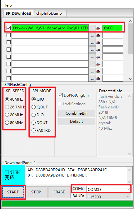
Proceed to the download page, enter the bin file to be programmed along with its corresponding programming address. Tick the checkbox preceding the bin file, then input
SPI SPEED,SPI MODE,COMandBAUDaccording to your specific requirements. -
Click
STARTto commence the download. During this process, the download tool will read the flash information and the chip's MAC address. -
Upon completion of the download, the tool's interface will appear as shown in the figure below.
01_LED_RGB
Programme Description
-
Testing the functionality of the LTH1010RGB RGB LED controlled by GPIO48 in the W11 product, including communication between the LED and ESP32S3, and the display and dimming functions for red, green, and blue colours.
-
The RGB LED cycles through red, green, and blue (each colour maintained for 1 second), followed by a 1-second off period. This process repeats continuously.
Hardware Connection
- Connect the board to your computer using a USB cable
Operational Output
- Open the serial monitor
- You will sequentially observe: LED displays red, LED displays green, LED displays blue, LED is off
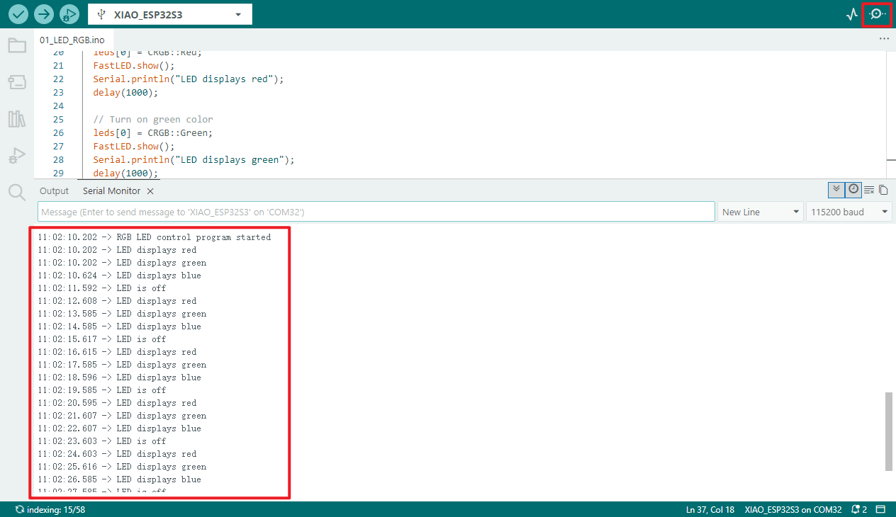
Board status:
02_SD_Test
Programme Description
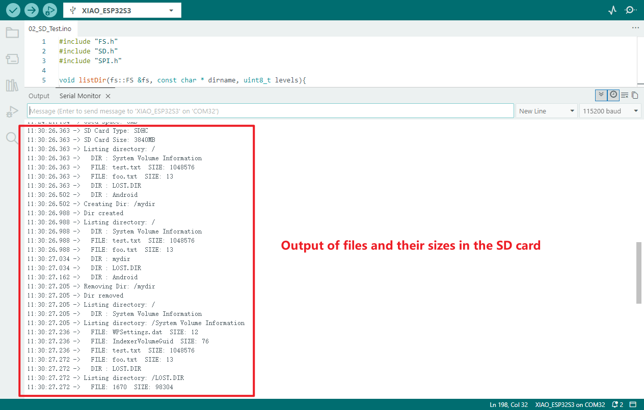
FS.h handles file operations, SD.h interfaces with microSD cards, and SPI.h utilises the SPI communication protocol
- SD card directory management:
- List root directory contents (non-recursively)
- Create "mydir" directory and print result
- Relist root directory to verify
- Delete "mydir" and print result
- Recursively list all contents of root directory to two levels
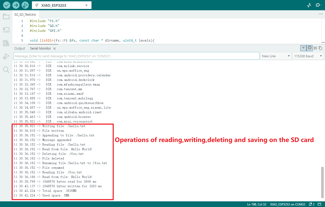
- SD card file operations:
- Create "hello.txt" and write "Hello "
- Append "World!\n"
- Read contents and output via serial port
- Attempt to delete "foo.txt"
- Rename "hello.txt" to "foo.txt"
- Read "foo.txt" to verify integrity (print operation results at each step)
- SD card I/O performance testing:
- Read full contents of "test.txt" (record byte count / elapsed time), write 1048576 bytes of data (record byte count / elapsed time), output both via serial port
- Storage capacity statistics:
- Calculate and print total capacity and used capacity (in MB) of SD card via serial port
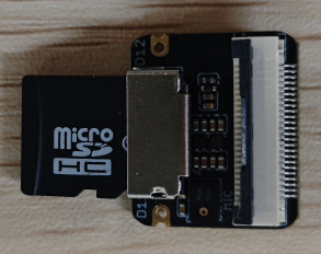
Hardware connection
- Connect the board to the computer using a USB cable
- Insert the SD card into the designated card slot
Operational Effect
- Open the serial monitor
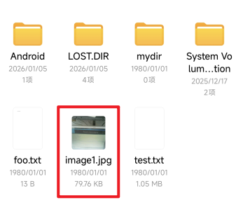
- A card reader may be used to inspect the internal state of the SD card; the diagram below illustrates the content viewable via mobile phone.
- Final SD card contents:
- Two new files will be created: one named
test.txtand another namedfoo.txt. - The
foo.txtfile will contain the text "Hello World!". - The
test.txtfile is used to test the speed of reading the entire file content, as well as to calculate the total file size and the time taken to read all data.
- Two new files will be created: one named
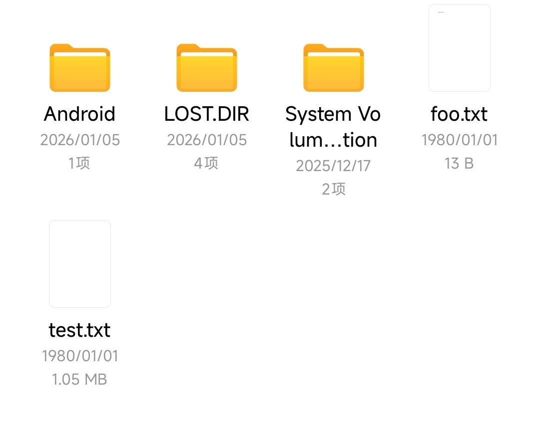
- Contents of the
foo.txtfile

03_DVP_Camare_SaveSD
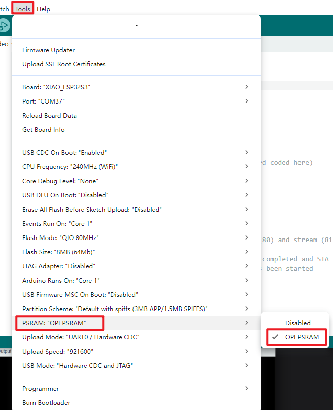
Programme Description
Arduino IDE Supplementary configuration
The ESP32's PSRAM refers to the external PSRAM (Pseudo-Static Random Access Memory) on the ESP32 chip, which provides additional memory space to augment the available memory of the ESP32 system. Within the ESP32 system, PSRAM serves the following primary purposes:
-
Expanding available RAM: The ESP32's built-in RAM is limited, particularly for applications requiring substantial memory such as image processing or audio processing, where the internal RAM may prove insufficient. Utilising PSRAM enables the expansion of the ESP32's available RAM to meet the demands of such applications.
-
Accelerating memory access: Whilst PSRAM is external memory and thus slower than internal RAM, it can serve as cache or temporary storage to expedite memory access and data processing.
-
Storing buffers: For applications requiring substantial buffers—such as network buffers or audio buffers—PSRAM provides ample storage capacity to prevent memory shortages.
For the purposes of this tutorial, you must enable the PSRAM feature within the Arduino IDE to ensure the camera functions correctly.
- Define hardware communication pins: Default configuration for XIAO ESP32S3 (with PSRAM) camera, SD card select pin = 21, supports custom modification
- Configure core camera parameters: Set 20MHz clock, UXGA frame size, JPEG format; automatically adjusts JPEG quality and frame buffer based on PSRAM
- Camera module self-test: Executes camera initialisation, prints success/error codes via serial port to verify hardware functionality
- Initialise SD card: Mounts SD card using GPIO21 as chip select, prints mount success/failure via serial port to validate storage module
- Detect SD card information: Identifies and outputs SD card type via serial port; terminates storage process if no valid card is present
- Mark SD Card Ready: Flag status once SD card is normal; photo capture only triggers when both camera and SD card are ready
- Configure timed photography: Default 60-second interval, triggered by millisecond-accurate timing, supports adjustable capture frequency
- Generate incrementing filenames: Automatically creates files like /image1.jpg, prevents overwriting, supports continuous storage
- Capture JPEG images: Retrieves camera image buffer upon trigger, extracts complete image data
- Save images to SD card: Writes images to corresponding files, serial port prints success/failure status to confirm storage validity
- Release image buffer: Frees frame buffer after saving to prevent memory leaks and ensure stable operation
- Incremental photo sequence numbering: Updates file sequence numbers to guarantee unique filenames, supporting uninterrupted continuous capture and storage.
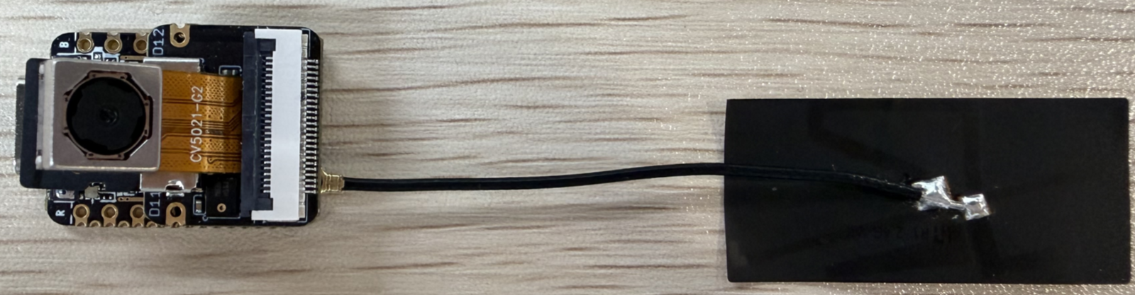
Hardware Connection
- Connect the board to the computer using a USB cable
- Both the camera and SD card must be connected to the expansion board
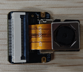
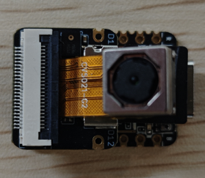
SD card:

Camera:
Complete connection (expansion board to mainboard):
Operational Results
- Upon opening the serial monitor, prompt outputs for each step can be observed.
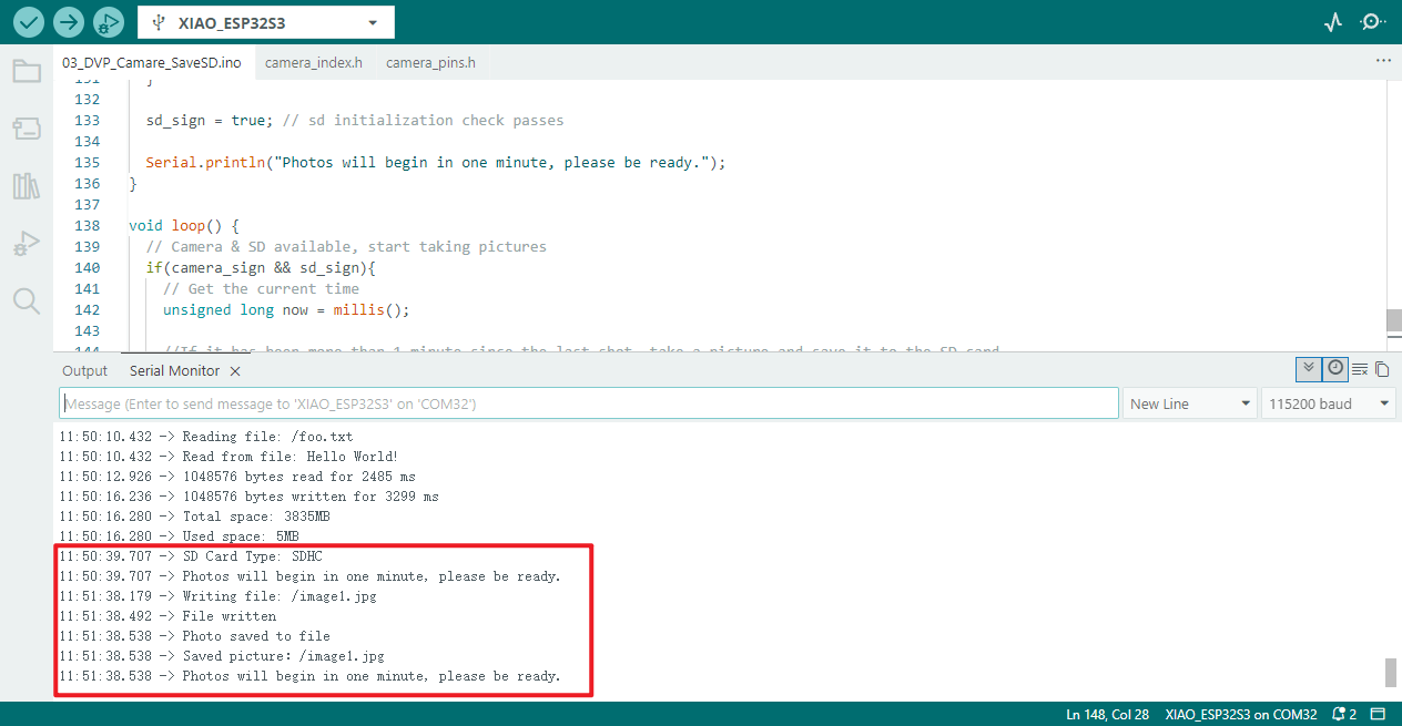
- Board status: Remove the SD card, use a card reader, and check whether photographs have been captured and saved.
04_QMI8658C_IMU
Programme Description
- Defining Sensor Communication / Interrupt Pins: By default, I²C communication pins are defined as SDA=5 and SCL=4, with the interrupt pin set to IRQ=-1 (interrupts currently disabled). Custom pin modifications are supported.
- Sensor Self-Test Functionality: Performs separate self-tests for the accelerometer and gyroscope, printing self-test success/failure results to the serial port to verify sensor hardware integrity.
- Accelerometer Parameter Configuration: Sets accelerometer range to 4G, data output rate to 1000Hz, low-pass filter mode to 0 (filtering high-frequency noise).
- Gyroscope Parameter Configuration: Sets gyroscope range to 64°/s, data output rate to 896.8Hz, low-pass filter mode to 3 (enhanced noise filtering capability).
- Enable core detection functionality: Activate both accelerometer and gyroscope simultaneously; when operating concurrently, the output frequency defaults to the gyroscope's rate (896.8Hz).
- Support optional interrupt configuration: Defining IMU_INT>0 enables interrupt pin 1 and disables interrupt pin 2, reserving an interface for subsequent interrupt-triggered data reads.
- Data Readiness Detection: Cyclically checks whether sensor data acquisition is complete, reading only when data is ready to prevent invalid data acquisition.
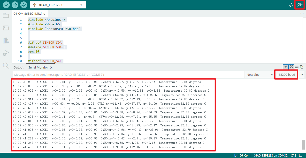
- Read and Print Accelerometer Data: Reads x/y/z axis data from the accelerometer and prints specific values via the serial port, supporting subsequent visualisation with a serial plotter.
- Read and print gyroscope data: Retrieve angular velocity data from the gyroscope's x/y/z axes, printing specific values via the serial port to reflect the device's rotational state.
- Read and print sensor temperature: Continuously monitor the sensor's internal temperature (in degrees Celsius), outputting readings via the serial port to assist in monitoring the device's operating environment.
Hardware Connection
- Connect the board to the computer using a USB cable
Operational Results
- Open the serial monitor to view the serial port output information
- Specific details of the current IMU can be observed
05_ADC
Programme Description
- Configure ADC Acquisition Pins: Set designated GPIO pins to ADC data acquisition mode, ensuring no conflicts with other peripherals
- Print ADC Debug Information: Output programme name, ADC configuration details, and data output format via serial port for subsequent debugging and troubleshooting
- Optimise ADC Data Anti-Interference: Perform multiple acquisitions of the same measurement, summing and averaging the results to reduce interference and enhance data stability
- Read and Aggregate Raw ADC Data: Read 12-bit precision raw ADC data (range 0-4095), complete data organisation and aggregation
- Calculate and Correct Actual Voltage: Calculates the pin input voltage based on reference voltage and acquisition precision, applying voltage divider ratio correction to derive the true actual voltage
- Formatted output of ADC detection results: Prints ADC raw values and final actual voltage via serial port in a clear format for intuitive data comprehension
- Configuration of ADC cyclic sampling parameters: Sets a 1-second sampling interval for continuous ADC detection, perpetually outputting the latest detection results
Hardware Instructions
- Connect the board to your computer using a USB cable
Operational Results
- Open the serial monitor to verify whether the programme outputs correct voltage values
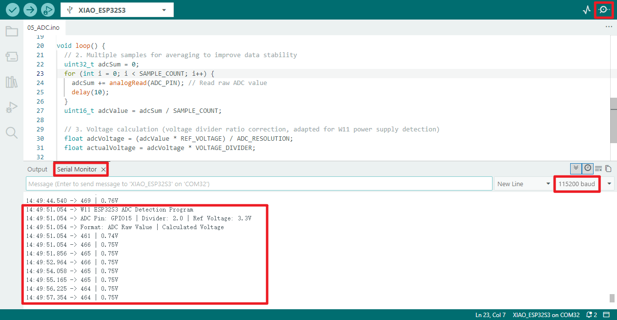
📌The serial monitor displays an output value of 0.75V. This occurs because the programme has configured GPIO pin 15, yet the device lacks soldered header pins → the ADC pin remains floating → preventing reception of the VCC_3V3 voltage divider signal.
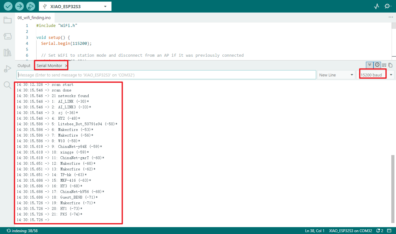
06_wifi_finding
Programme Description
- Configure WiFi operating mode: Set WiFi to Station (STA) mode, disconnecting any existing AP connections
- Stabilise WiFi configuration state: Introduce a 100-millisecond delay to ensure WiFi mode switching takes effect
- Print initialisation completion prompt: Output "Setup done" via serial port to inform the user that programme initialisation is complete
- Initiate nearby WiFi scan: Trigger WiFi network scan to obtain count of available nearby WiFi networks
- Report no available networks: If no WiFi networks detected, serial port prints "no networks found" prompt
- Output total WiFi networks: Upon detecting available networks, serial port prints total count of found WiFi networks
- Iteratively print individual WiFi details: Sequentially print each WiFi's ID number, SSID, signal strength (RSSI), and indicate encryption status (unencrypted networks lack *, encrypted networks display *)
- Configure scanning interval: After each scan completes, introduce a 5-second delay before initiating the next WiFi scan to prevent frequent scanning from consuming resources
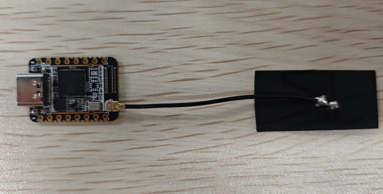
Hardware Connection
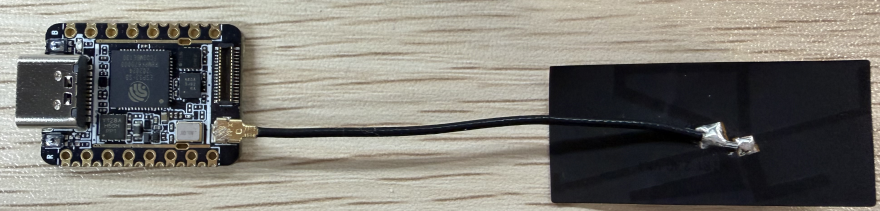
A dedicated "WiFi/BT Antenna Connector" is located at the bottom left corner of the board's front surface. To ensure optimal WiFi and Bluetooth signal quality, the accompanying antenna supplied in the packaging must be installed onto this connector.
Do not apply direct force to the antenna connector, as this may cause installation difficulties and potentially damage your hands or the connector itself. The correct procedure is as follows:
- Align one side of the antenna connector with the connector slot and insert it.
- Gently press the other side of the connector until it clicks firmly into place, completing the installation.
When dismantling, do not pull the antenna with excessive force to avoid damaging the connector or antenna interface. The correct procedure is as follows:
- Align the antenna connector with one side and gently apply upward pressure.
- Once that side has disengaged from the slot, the entire antenna can be easily removed.
❗note
- If the antenna is not installed, you may be unable to connect to WiFi networks.
- If circumstances permit, I recommend using a whip antenna for a superior experience.
- Next, connect the board to the computer using a USB cable and flash the program.
Operational performance
- Open the serial monitor to view all scanned Wi-Fi information: serial number, SSID, signal strength (RSSI), and whether encryption is enabled (unencrypted networks display no *, encrypted networks display an *).
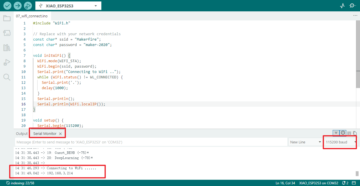
07_wifi_connect
Programme Description
This procedure connects the ESP32S3 Mini Module to a specific Wi-Fi network; you must know its SSID and password. Furthermore, the network must be within the ESP32S3 Mini Module's Wi-Fi range (to verify this, you may use the preceding example to scan for Wi-Fi networks).
- Define WiFi connection credentials: Pre-configure the WiFi name (SSID) and password for the network to connect to, facilitating subsequent modification of network settings
- Configure WiFi Initial Mode: Set WiFi to Station (STA) mode, disconnecting from any existing wireless AP connections
- Stabilise WiFi Initial State: Introduce a 100-millisecond delay to ensure WiFi mode switching and disconnection take effect
- Invoke WiFi Connection Function: Execute the custom initWiFi function to initiate the WiFi connection process
- Initiate WiFi connection request: Within the connection function, pass the predefined WiFi name and password to establish the network link
- Feedback WiFi connection progress: During connection, the serial port continuously prints "." to visually indicate the connection status
- Loop to await connection completion: Continuously monitors WiFi connection status, persisting until connection succeeds
- Output successful connection result: Upon successful WiFi connection, the serial port prints the device's assigned local IP address
- Maintain WiFi connection state: The loop function is empty, ensuring the established WiFi connection is sustained without additional looping operations
Below is an example of connecting to a specified network using the ESP32S3 Mini Module. The function initWiFi() serves to establish the network connection within the programme.
Both the target Wi-Fi network's ID and Password must be entered within the programme.
// Replace with your network credentials

const char* ssid = "Target WiFi SSID";

const char* password = "Target WiFi Password";
Hardware connection
- Connect the board to the computer using a USB cable
- Connect the antenna to the board (refer to the hardware connection section in [[#06_wifi_finding]] for specific instructions)
Operational performance
- Print the IP address assigned upon successful connection.
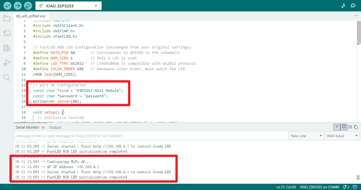
08_wifi_softAP�
Programme Description
- Configure FastLED RGB LED parameters: Define LED data pins 48, 1 LED lamp, WS2812 protocol, GRB colour sequence to establish LED control fundamentals
- Configure WiFi Access Point and HTTP Server: Set AP name and password, create HTTP server on port 80 for web-based LED control
- Initialise FastLED Functions: Load LED configuration, set brightness to 50, initialise LEDs to off state and apply settings
- Launch WiFi Hotspot: Create custom-named WiFi AP hotspot, serial port prints hotspot IP address
- Launch HTTP web server: Open port 80 server, serial port prompts to access specified IP for LED control
- Monitor client connection requests: Continuously detect devices connecting to the HTTP server associated with the WiFi hotspot
- Report client connection status: When a new device connects, serial port prints client connection success prompt
- Receive and parse client HTTP requests: Read web access data sent by clients, organise and parse request content
- Push LED control webpage: Return a webpage containing "Light On / Light Off" LED links to connected devices, supporting click operations
- Control LED to illuminate green: Upon parsing a "/H" request, set LED to green and apply effect, printing illumination confirmation via serial port
- Control LED to extinguish: Upon parsing a "/L" request, set LED to black (extinguish) and apply effect, printing extinguishment confirmation via serial port
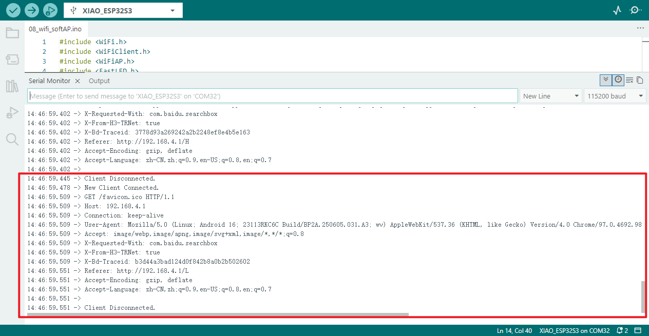
- Close client connection and provide feedback: Upon request completion, disconnect the client connection and print a client disconnection prompt via serial port
- Loop to await new requests: The programme runs continuously, awaiting the next device connection and processing LED control commands
This example demonstrates the setup process for the ESP32S3 Mini Module in AP mode, along with the web interface accessible via hotspot connection. It implements a remote control solution for switching the lighting fixture on and off.
Upon successful Wi-Fi connection, visiting the designated website enables control of the green light's illumination status via the web interface.
// WiFi AP Configuration
const char *ssid = "ESP32S3 Mini Module";
const char *password = "password";
//You can modify the password to be configured.
Hardware connection
- Connect the board to the computer using a USB cable.
- Connect the antenna to the board (refer to the hardware connection section in [[#06_wifi_finding]] for specific instructions).
Operational performance
- Serial port output information; access the corresponding URL as per the prompt message.
- Once the connection is established, you may also view the detailed information of the connected device within the serial monitor.
- Mobile device
Connect using the configured password
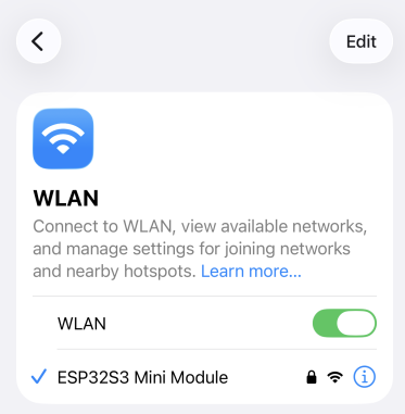
Enter http://192.168.4.1 in your web browser to access the interface for controlling the light switch.

- Equipment status
| ON | OFF |
|---|---|
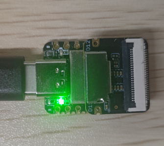 | 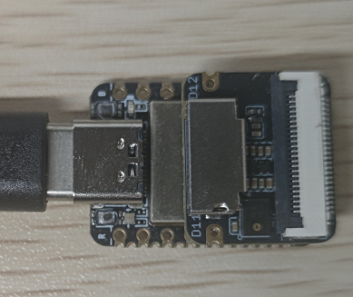 |
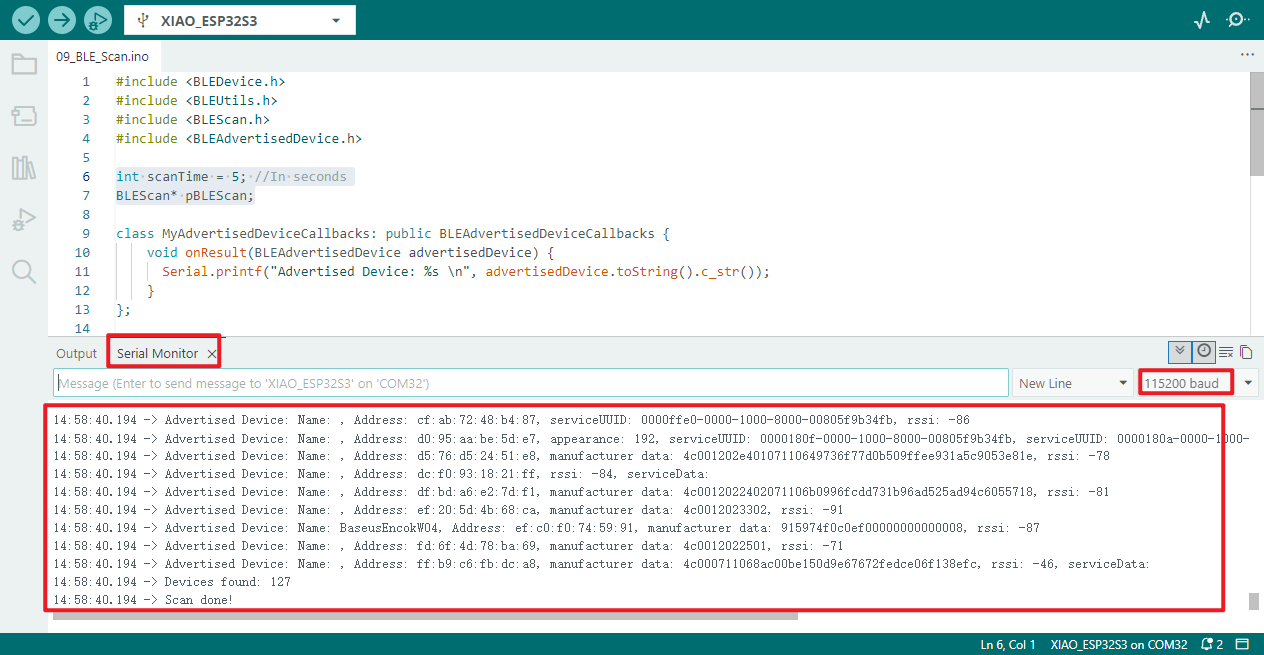
09_BLE_Scan
Function Overview
Bluetooth Low Energy (BLE) is an energy-optimised variant of traditional Bluetooth technology, designed primarily for short-range, low-bandwidth wireless data transmission involving small data volumes.
- BLE employs a distinct operating mechanism from conventional Bluetooth, remaining inactive most of the time rather than maintaining a constant active state. It enters operational mode only when establishing connections and executing data transfers, spending the majority of its time in a low-power sleep state.
- Thanks to its unique low-power operating mode, BLE significantly reduces energy consumption. Across various practical use cases, its power consumption is approximately one per cent of that of traditional Bluetooth.
- BLE's characteristics make it particularly suitable for devices powered by button batteries, requiring long-term stable operation, and needing only to exchange small amounts of data periodically.
- BLE has extensive application scenarios, commonly found in healthcare devices, fitness equipment, various trackers, wireless beacons, security devices, and smart home products.
Server and Client
The ESP32S3 Mini Module development board supports flexible role switching, functioning either as a server or configurable for client operation.
- BLE Server Device: Its core function is to actively broadcast its presence signal for discovery and identification by neighbouring BLE devices. The server internally stores data resources accessible for reading and retrieval by client devices.
- BLE Client Device: Its core behaviour involves actively scanning for BLE devices within range. Upon detecting and matching a target server device, it initiates a connection request to establish a stable communication link, subsequently listening for or retrieving incoming data from the server device.
- This communication interaction between BLE servers and clients falls within the realm of peer-to-peer (P2P) communication, representing a fundamental and prevalent communication form within BLE technology.
Core Definition of Data Transmission
Attributes (data entries)Underlying data → ATT Protocol Underlying Commands / Packets → GATT AgreementHigh-Level Organisation / Transmission Rules → Ordered data transmission between BLE devices (sensor data, control commands, etc.), forming a complete logical closed loop for BLE data transfer.
-9c8d3cbc95f3ae75043b52042ccae12e.jpg)
Programme Description
- Incorporate BLE core library files: Provide foundational support for ESP32 BLE scanning functionality
- Define core BLE scanning parameters: Set 5-second scan duration and declare BLE scan object pointer
- Customise BLE device callback class: Implement logic to print device details upon detecting BLE devices
- Print scan initiation prompt: Serial output "Scanning..." to indicate imminent BLE scan commencement
- Initialise BLE device: Initialise ESP32 BLE device without setting custom device name
- Create and bind BLE scan callback: Obtain BLE scan instance and bind callback to process scan results
- Enable BLE active scan mode: Initiate active BLE scanning to rapidly acquire nearby device information
- Configure BLE scan timing parameters: Set scan interval to 100ms and scan window to 99ms for optimised efficiency
- Execute scheduled BLE scan: Initiate a 5-second BLE scan to retrieve results of nearby visible BLE devices
- Output total scanned devices: Print the number of BLE devices detected during this scan via serial port
- Print scan completion prompt: Output "Scan done!" via serial port to indicate conclusion of BLE scan
- Clear scan results to free memory: Clear old data from the BLE scan buffer to release occupied memory
- Set scan cycle interval: After scan completion, delay for 10 seconds before initiating the next BLE scan
Hardware connection
- Connect the board to your computer using a USB cable.
- Attach the antenna to the board (refer to the hardware connection section in [[#06_wifi_finding]] for specific instructions).
Operational performance
- View the port monitor, which displays the names, MAC addresses, manufacturer details, and signal strength of detected Bluetooth devices.
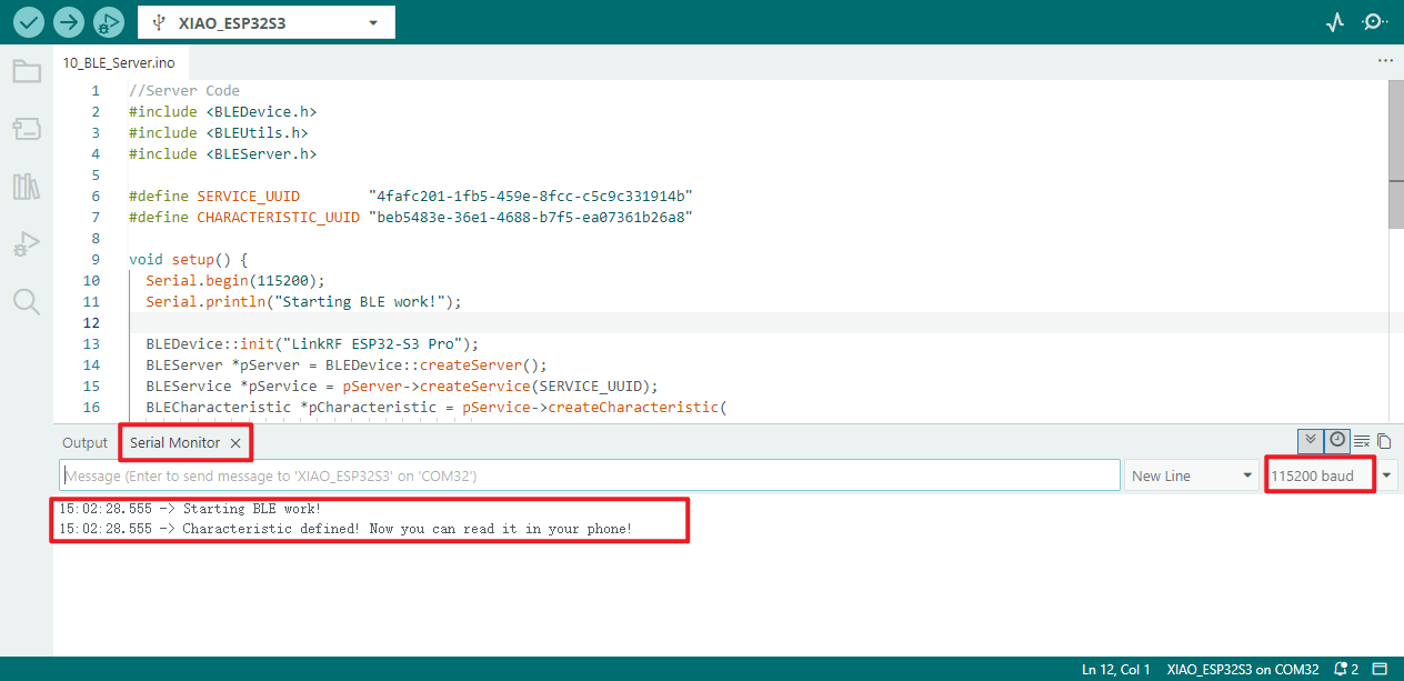
10_BLE_Server
Programme Description
- Initialise BLE device: Set device name to "ESP32S3 Mini Module", completing basic BLE device initialisation configuration
- Create BLE service instance: Establish BLE server instance, creating corresponding BLE service based on specified service UUID
- Create and configure BLE characteristic: Create BLE characteristic based on specified characteristic UUID, configuring support for both "read" and "write" operation permissions
- Set BLE Characteristic Initial Data: Pre-populate the created BLE characteristic with initial data "Hello World", completing data initialisation
- Activate BLE Service: Enable the created BLE service, placing it in an accessible state for neighbouring devices
- Configure BLE Broadcast Parameters: Retrieve the BLE broadcast instance, add the service UUID to broadcast content, enable scan response, and set minimum preference value (Resolves iPhone device connectivity compatibility issues)
- Initiate BLE broadcasting and print prompt: Enable BLE broadcasting functionality, print serial port prompt indicating the characteristic is defined and readable via mobile device
- Sustain BLE operational state: Main loop executes a fixed 2-second delay with no additional business logic, continuously maintaining normal operation of the BLE server and broadcast
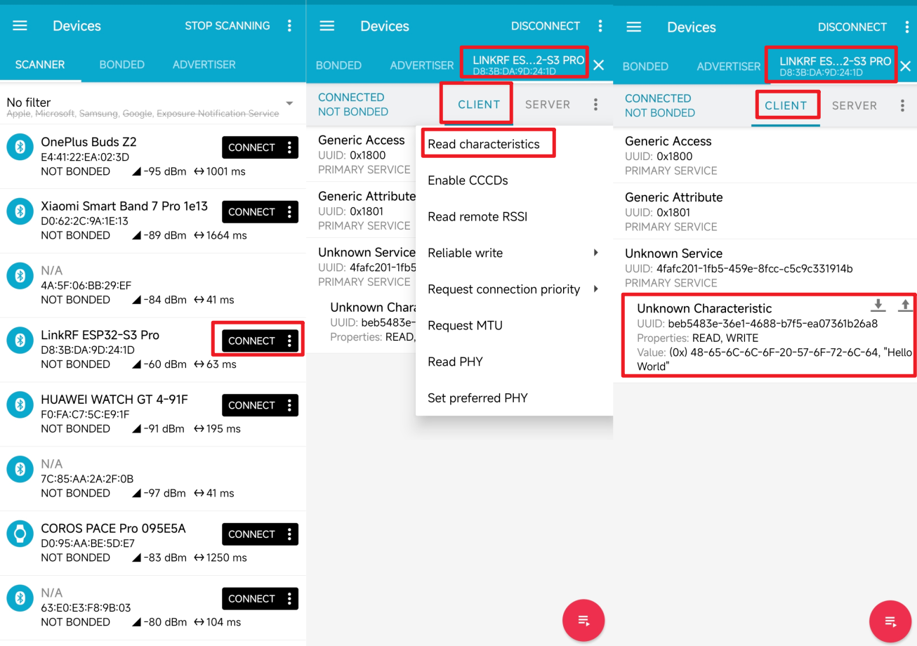
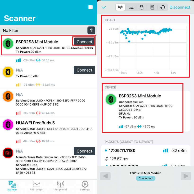
You may search for and download the nRF Connect application from the major mobile app stores. This application enables your mobile phone to search for and connect to Bluetooth devices.
- Android:nRF Connect
- IOS:nRF Connect
UUID
Each service, feature, and descriptor possesses a UUID (Universally Unique Identifier). A UUID is a unique 128-bit (16-byte) number. For example:
ea094cbd-3695-4205-b32d-70c1dea93c35
For all types, services, and profiles specified within the SIG (Special Interest Group for Bluetooth), abbreviated UUIDs are provided. However, should your application require its own UUID, you may utilise this UUID generator website to generate it.
Hardware connection
- Connect the board to your computer using a USB cable.
- Attach the antenna to the board (refer to the hardware connection section in [[#06_wifi_finding]] for specific instructions).
Operational performance
- Open the serial port monitor to check whether the service is running.
- Using the
nRF Connectsoftware on a mobile device allows you to connect to the server and receive the transmitted dataHello World.
Android:
iOS:
Click the Connect button to connect to the server.
You may select the type of data to receive and view the transmitted data Hello World.
11_BLE_Client
Programme Description
If you wish to use another ESP32S3 Mini Module as a client to receive messages from the server, you may employ the following programme for the client.
- Define target BLE identifier: Specify the target BLE service/profile UUID to identify the device to be connected
- Configure BLE active scan parameters: Set a 5-second scan duration and initiate scanning to locate the target BLE device
- Terminate scan and mark status: Cease scanning upon detecting the target BLE device, marking it as ready for connection
- Connect to Target BLE Server: Establish connection with the target BLE server, configure client callbacks, and set MTU value to 517
- Verify BLE Services and Characteristics: Validate the existence of the target BLE service and characteristics; disconnect if absent
- Configure BLE Data Monitoring: Enable reading BLE characteristic values and register notification callbacks to monitor server-pushed data
- Print BLE Notification Data: Upon receiving a BLE server notification, print the characteristic UUID, data length, and specific content via serial port
- Scheduled BLE Data Writing: Upon successful connection, writes the device's power-on duration string to the target BLE characteristic value every second
- Cyclic Device Reconnection Attempts: After BLE disconnection, restarts scanning and continuously cycles through attempts to reconnect to the target BLE device
The parameter content in the following programme must correspond to the server's UUID.
// The remote service we wish to connect to.

static BLEUUID serviceUUID("4fafc201-1fb5-459e-8fcc-c5c9c331914b");

// The characteristic of the remote service we are interested in.

static BLEUUID    charUUID("beb5483e-36e1-4688-b7f5-ea07361b26a8");
The aforementioned procedure will configure the ESP32S3 Mini Module as a client to scan for nearby Bluetooth devices. When the UUID of a Bluetooth device matches the one you provided, it will connect to that device and retrieve its characteristic values.
Hardware connection
- Connect the board to your computer using a USB cable.
- Attach the antenna to the board (refer to the hardware connection section in [[#06_wifi_finding]] for specific instructions).
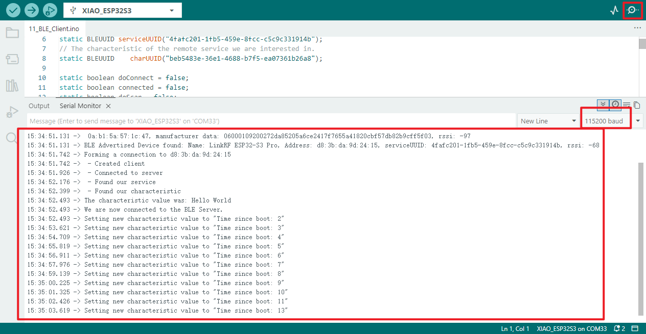
Operational performance
- When the Bluetooth device's UUID matches the one you provided:
- The serial port will output a single batch of prompt messages indicating BLE client creation, server connection, specified service/characteristic value lookup, initial characteristic value read results, and connection completion.
- During the connection, a prompt setting a new characteristic value (seconds since device power-on) will be periodically output every second. Should the remote server trigger a notification, the characteristic value, data length, and specific content of the notification will also be printed additionally.
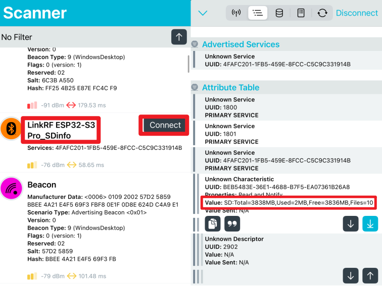
12_BLE_Sensor
Programme Description
- Configure BLE and SD card basic parameters: Set BLE service/profile UUIDs compatible with legacy clients, designate SD card select pin as 21
- Read and print SD card initialisation information: Retrieve total capacity, used capacity, available capacity (in MB) and root directory file count; print relevant information via serial port
- Initialise BLE server and create characteristics: Establish BLE server (device name: LinkRF ESP32-S3 Pro_SDinfo), create BLE characteristics supporting "read" and "notification" types
- Initiate BLE broadcast and await connection: Configure BLE broadcast parameters and commence broadcasting, awaiting connection from nearby BLE client devices
- Handle BLE client connection callbacks: Trigger corresponding callbacks upon client connection or disconnection; automatically restart BLE broadcasting after disconnection
- Periodically read and format SD card status: After successful client connection, read real-time SD card status every second and format the data
- Push SD card data to BLE clients: Update BLE characteristic values to actively push formatted SD card data to connected BLE clients
- Serial port debugging output for SD card data: Print SD card data pushed to BLE clients via the serial port for subsequent debugging and troubleshooting
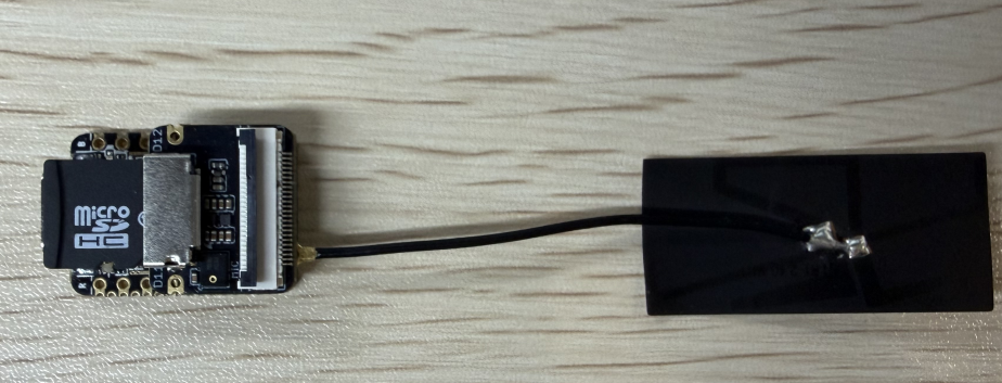
Hardware connection
- Connect the board to your computer using a USB cable.
- Attach the antenna to the board (refer to the hardware connection section in [[#06_wifi_finding]] for specific instructions).
- Insert the SD card into the expansion board and connect the expansion board to the main board.
Operational Results
- Open the serial monitor to verify whether the service has been successfully initiated.
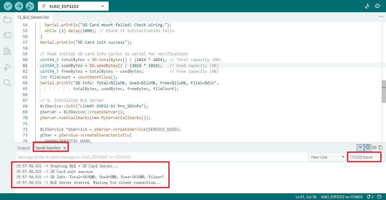
- Use the
nRF Connectsoftware on your mobile device to check whether it can receive information from the SD card.
Android:
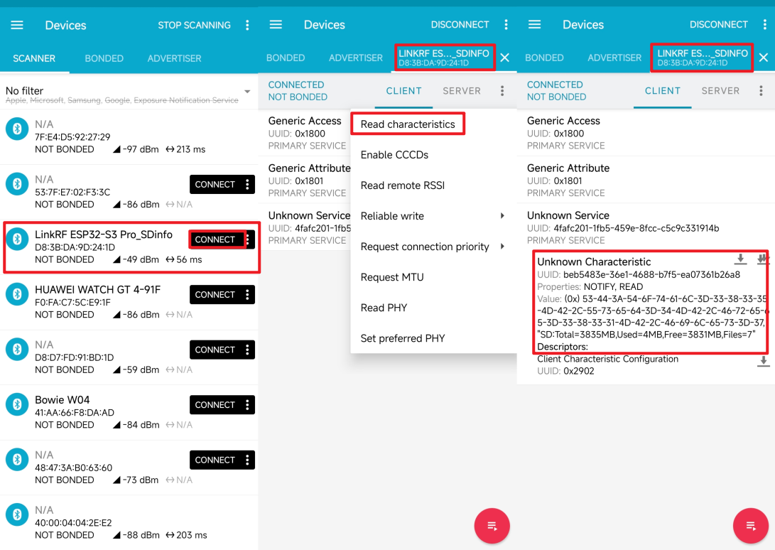
IOS:
- Should you be interested in this functionality, you may modify this programme to incorporate additional detection components within the device and utilise Bluetooth capabilities for data transmission.
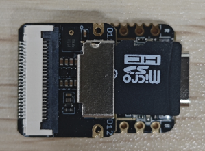
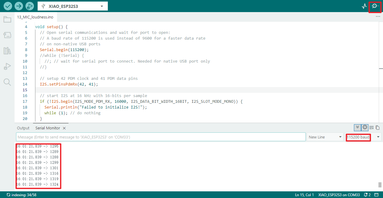
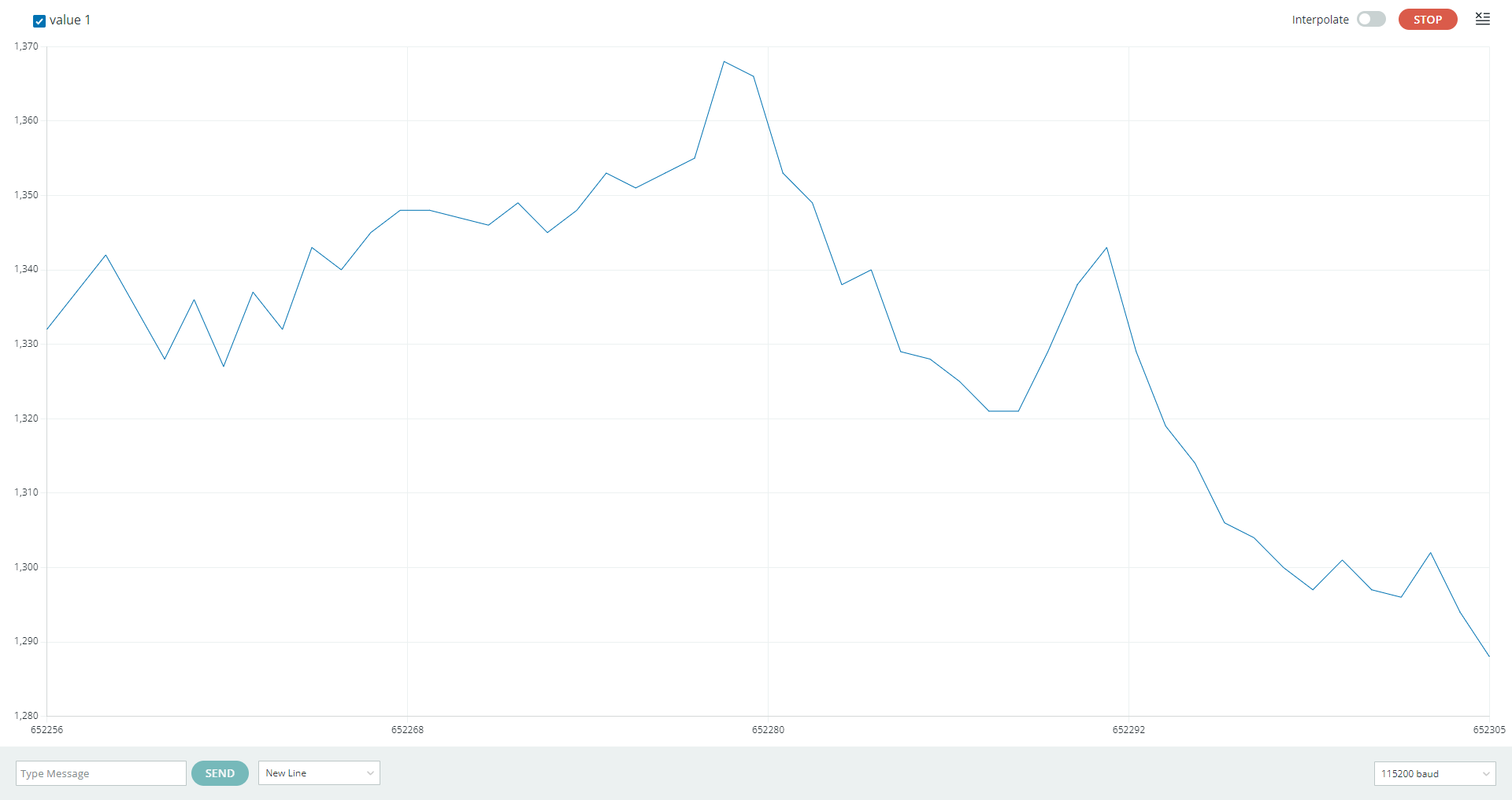
13_MIC_loudness
Programme Description
- Configure I2S PDM Receive Pins: Designate pin 42 as the I2S CLK pin and pin 41 as the DATA pin to complete PDM receive pin configuration
- Initialise I2S PDM reception parameters: Configure I2S for PDM reception mode, setting a 16kHz sampling rate, 16-bit data width, and mono acquisition
- Handle I2S initialisation exceptions: Should I2S initialisation fail, output a warning message via the serial port and block further programme execution
- Read and filter PDM sample data: Iteratively read I2S PDM sample values, filtering out invalid values such as -1, 1, 0
- Serial port output of valid PDM audio data: Print filtered valid PDM audio sample data via the serial port for convenient viewing of acquisition results
Hardware connection
- Connect the board to the computer using a USB cable.
- Connect the expansion board to the mainboard, as the microphone is located on the expansion board.
Operational performance
- Open the serial monitor to view the specific values.
- Upon opening the serial port plotter, one can observe the icon data.
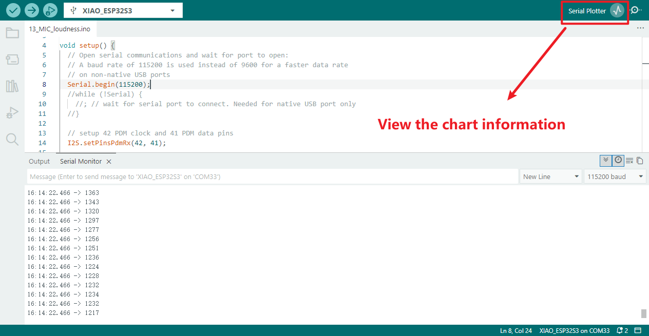
- Concrete manifestation.
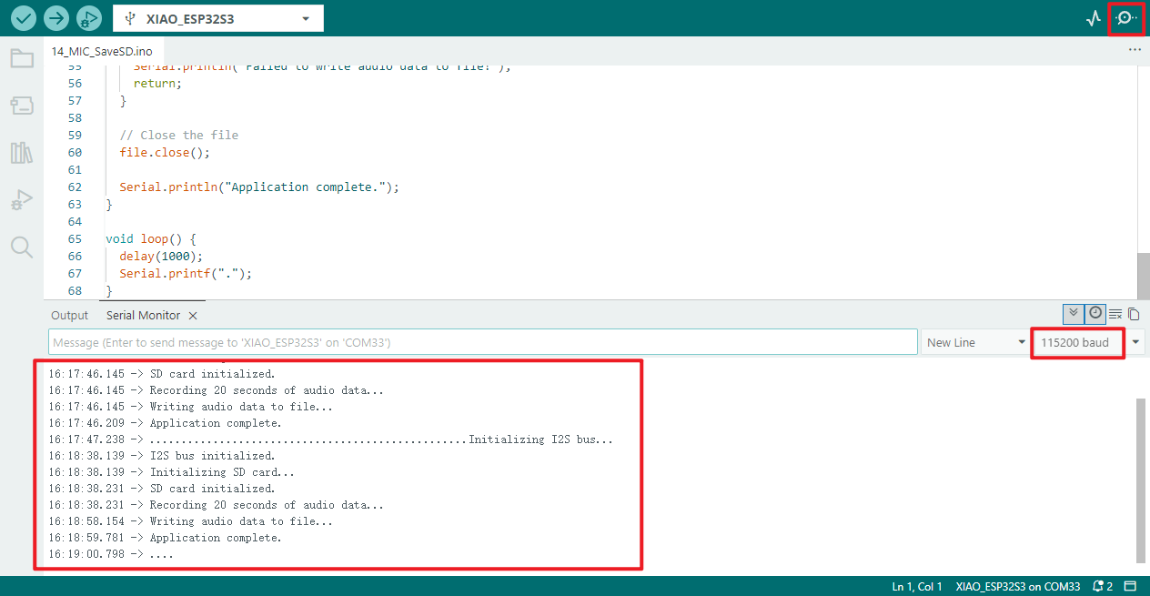
14_MIC_SaveSD
Programme Description
- Configure I2S PDM Receive Pins: Designate pin 42 as the I2S CLK pin and pin 41 as the DATA pin to complete PDM receive pin configuration
- Initialise I2S PDM Receive Mode: Configure I2S for PDM receive mode with a 16kHz sampling rate, 16-bit data width, and mono operation. Block programme execution if initialisation fails
- Initialise SD card and configure chip select pin: Designate SD card chip select pin as 21, perform SD card initialisation and mount; if mount fails, block programme execution
- Record audio and generate WAV format cache: Capture 20 seconds of audio data, create a WAV format data cache, and obtain the total size of this audio data
- Create and open SD card audio file: Create or open the "arduinor_rec.wav" file on the SD card; if file opening fails, terminate subsequent audio write operations
- Write WAV data and verify write outcome: Write the generated WAV audio cache data to the file, verify the written data length, and output a prompt message if writing fails
- Sustain programme operation and print status: The main loop prints a dot per second via the serial port, with no additional business logic, continuously maintaining normal programme operation
Hardware connection
- Connect the board to the computer using a USB cable
- Attach the expansion board to the mainboard, as the microphone is located on the expansion board
- Insert the SD card into the card slot
Operational performance
- Open the serial monitor to verify whether the function is activated correctly.
- View the contents of the SD card to check whether any WAV audio files have been saved.
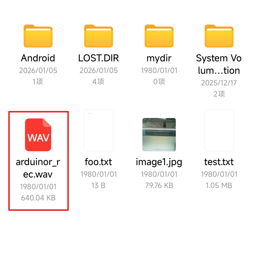
- Upon clicking to open, the audio plays correctly.
15 SleepFunction
Deep sleep
Programme Description
In deep sleep mode, the ESP32 deactivates the CPU, most RAM, and all digital peripherals driven by the APB_CLK clock. Only the following components remain powered:
- RTC controller
- ULP coprocessor
- RTC fast memory
- RTC slow memory
Wake-up Methods:
- Timer Wake-up: The ESP32 can be configured to automatically wake up after a specified time via a timer.
- Touchpad Interrupt Wake-up: The device can be awakened by touchpad activity, suitable for applications requiring user interaction.
- External Wake-up: The ESP32 can be awakened by external signals (such as button presses), ideal for low-power applications.
- ULP Coprocessor Activity Wake-up: The ULP coprocessor operates independently, monitoring specific conditions and waking the main CPU to conserve power.
- GPIO Wake-up: The device may be awakened by changes in GPIO pin states (high or low), offering flexibility for various sensors and peripherals.
‼️ Important Notice Should the ESP32S3 Mini Module enter sleep mode and require reprogramming, it must be placed into programming mode. Follow these steps:
Disconnect the board's USB power supply (unplug the USB cable) to prevent operational errors during powered operation
Press and hold the
BOOTpin firmly (maintain pressure without releasing)Reinsert the USB cable to power the board (while still holding the
BOOTpin down), maintaining pressure for 1-2 secondsRelease the
BOOTpin. The board will now enter programming mode, and the device will appear as online in the Arduino IDE interface
Hardware connection
- Connect the board to the computer using a USB cable.
Operational performance
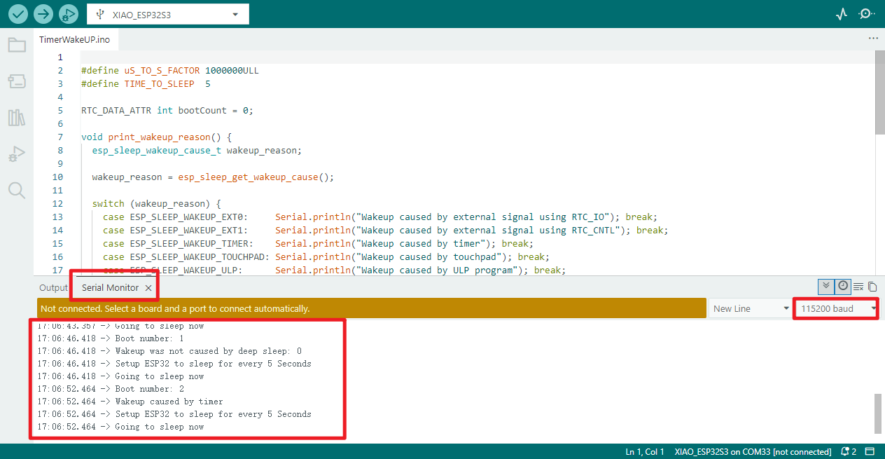
TimerWakeUP:
- Set the conversion value for microseconds to seconds, a 5-second sleep duration, and a dedicated storage area to record the number of device starts (sleep does not cause loss).
- Develop a function query to display the device wake-up cause via serial port (timed / external signal, etc.);
- Initiate serial port communication and wait for one second to ensure proper transmission;
- Start count incremented by one; serial port displays current start count.
- The function displays the reason for this wake-up, facilitating troubleshooting.
- Enable scheduled wake-up, set to automatically wake the device after 5 seconds;
- Serial port display hibernation settings, indicating imminent entry into deep hibernation;
- Refresh the serial port buffer to ensure all information is printed in full.
- The device enters deep sleep mode, after which the programme ceases operation.
- The main programme loop contains no additional functionality and performs no superfluous operations.
Operational effect:
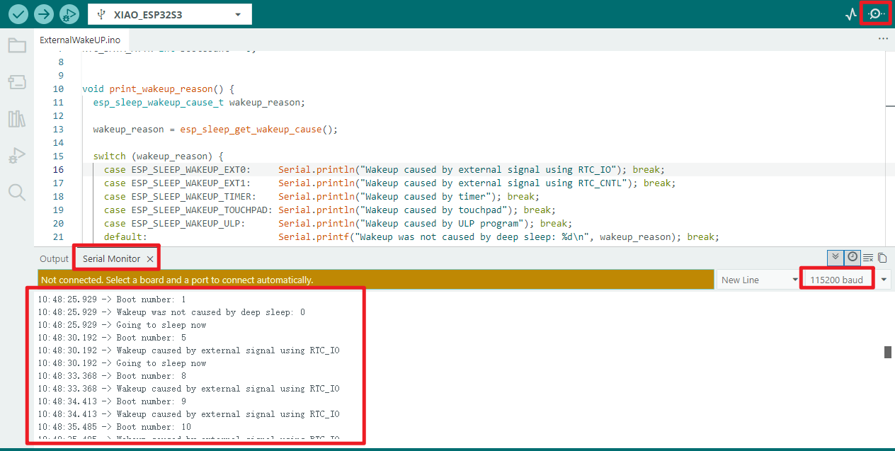
ExternalWakeUP:
- Import the tool library, configure the wake-up pin GPIO33 and its parameters, with dedicated memory recording the number of starts (non-volatile during sleep);
- Initiate serial port communication and wait for one second to ensure proper transmission;
- Start count incremented by one; serial port displays current start count.
- Invoke function to print the reason for the device's wake-up via serial port (for debugging purposes).
- Default EXT0 mode enabled: GPIO33 high level wakes the device;
- Configure GPIO33: Disable pull-up, enable pull-down to prevent erratic level fluctuations causing unintended wake-up;
- If EXT0 is disabled, EXT1 mode shall be enabled, with GPIO33 high level triggering wake-up;
- Serial port prompt: Device is about to enter deep sleep mode;
- The device enters deep sleep mode, ceasing execution of subsequent programmes, and awaits a high-level signal on GPIO33 to awaken.
- The main programme loop contains no additional operations and performs no superfluous functions.
Operational performance:
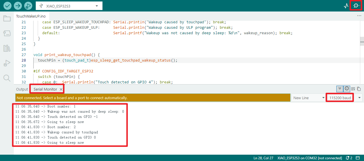
TouchWakeUP
- Configure different touch wake-up sensitivities according to the ESP32/S2/S3 chip model to adapt to hardware characteristics.
- A dedicated storage area records the number of boot-ups (persistent during sleep mode), while a reserved variable tracks the touch pin that triggered the wake-up.
- Develop a functional query and serial port printout to identify device wake-up causes (touch/timer-based, etc.);
- Develop a functional query and serial port printout for the touch pins that trigger wake-up (adapted to the chip model);
- Initiate serial communication and wait for one second to ensure proper transmission;
- Start count incremented by one; serial port displays current start count.
- Invoke the query function to print the wake-up cause and touch pin information (for debugging purposes);
- Configure touch wake-up based on chip model (enable two pins for ESP32, one pin for S2/S3), load preset sensitivity;
- Serial port prompt indicating imminent entry into deep sleep;
- The device enters deep sleep mode, ceasing execution of subsequent programmes, and awaits a touch signal to awaken.
- The main programme loop contains no additional operations and performs no superfluous functions.
Operational performance:
Light_sleep
Programme Description
Introduction:
Light Sleep Mode is a core low-power mode for the ESP32 series of chips, offering the dual advantages of high energy efficiency and rapid wake-up response.
In this mode, the CPU core enters a suspended state to reduce power consumption, while RAM and certain peripherals remain powered to ensure the device can rapidly wake and respond when triggered by external events.
Furthermore, Light Sleep Mode supports keeping WiFi and Bluetooth modules active, making it particularly suitable for applications requiring both low-power operation and the continuous maintenance of wireless communication connections.
Wake-up methods:
- Timer Wake-up: Supports preset wake-up intervals, enabling automatic device activation upon reaching specified times to fulfil periodic task execution requirements.
- External Interrupt Wake-up: Responds to various external hardware interrupt signals for wake-up, with typical scenarios including button presses and external sensor triggers.
- Network Activity Wake-up: Responds to incoming network packets to awaken the device, eliminating the need for continuous active status and enhancing power efficiency in wireless communication scenarios.
- GPIO Wake-up: Allows designated GPIO pins to be configured as wake-up sources. When a pin experiences a state change or detects a specific signal, it triggers the device to awaken from light sleep.
Note:
- Define two core parameters: the 10-second device light sleep duration and the control pin for the on-board LED, preparing for subsequent processes.
- Write an LED-specific task: illuminate the LED and print a prompt; maintain illumination for 1 second before extinguishing the LED and printing a prompt; automatically delete itself upon task completion to release resources.
- Configure wake-up functionality: Set up a 10-second timer-based wake-up function to automatically rouse the device from sleep at the designated time.
- Execute light sleep sequence: Print a sleep prompt via the serial port, then enter light sleep mode, operating at low power for 10 seconds.
- Trigger post-wakeup lighting task: Upon awakening, create and execute the LED control task to achieve a 1-second LED illumination followed by extinction.
- Prepare for next cycle: After completing the LED task, introduce a 1-second delay for process stabilisation before commencing the next "sleep - wake - lighting control" cycle.
- Achieving Periodic Low-Power Operation: The main loop contains no additional operations, continuously repeating the core process to implement periodic low-power lighting control.
Hardware Connection
- Connect the board to a computer using a USB cable.
Operational performance
Modem sleep mode(Modem_sleep)
Programme Description
Introduction:
Modem Sleep Mode is a significant low-power mode for the ESP32, operating distinctly from Deep Sleep Mode. Its core optimisation targets the ESP32's WiFi/Bluetooth wireless communication modules.
In this mode, the ESP32's WiFi and Bluetooth modules enter a dormant state to reduce power consumption, while the CPU core remains active. This approach significantly reduces the device's overall power consumption while retaining some wireless connectivity capability, balancing energy efficiency with fundamental operational requirements.
Wake-up methods:
- Timer Wake-up: Devices automatically awaken upon reaching preset fixed durations or precise time points when conditions are met, requiring no external intervention. Primarily suited for periodic tasks (such as scheduled data collection or cyclical status reporting).
- External Interrupt Wake-up: The device responds to interrupt signals generated by external hardware to achieve wake-up. Trigger sources include button presses, sensor threshold activations, or external device level changes. This method offers real-time responsiveness, suitable for scenarios requiring rapid detection of external events.
- Task Wake-up: Within multi-tasking operating systems (e.g., FreeRTOS), other ready tasks trigger the wake-up of designated dormant tasks via communication mechanisms such as semaphores, message queues, or event groups. This suits scenarios requiring inter-task coordination and on-demand execution (e.g., waking a foreground display task upon completion of background data processing).
- Network Activity Wake-up: The device responds to incoming network events—such as incoming network packets or connection requests—to awaken itself. This avoids maintaining the wireless module in high-power active mode continuously, balancing energy efficiency with the real-time nature of network communication. It is suitable for scenarios involving receiving cloud commands or network data exchange.
Note:
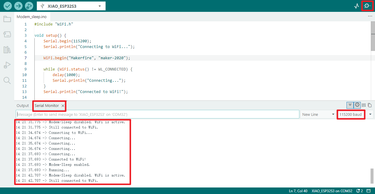
- Initialise the serial port at 115200 baud rate, printing "Connecting to WiFi..." to monitor operational status.
- Attempt to connect to the specified WiFi network name and password.
- Loop while awaiting WiFi connection, printing "Connecting..." every second until successful connection.
- Upon successful WiFi connection, the serial port prints "WiFi connected" as confirmation.
- Enable ESP32 modem sleep mode, print a prompt, and conserve WiFi module power.
- Main loop first prints "Program running", then delays for 5 seconds (maintaining WiFi power-saving).
- Disable modem sleep mode, print a prompt, and wake the WiFi module to active state.
- Check WiFi connection status, printing either "Connection maintained" or "Connection lost".
- Delay for 5 seconds (maintaining WiFi activity), then re-enable modem sleep mode and print a prompt.
- Continuously loop to implement a "WiFi power-saving 5 seconds - active 5 seconds" periodic cycle, balancing energy conservation with status monitoring.
WiFi.begin("****", "****");//Enter the WiFi SSID and password here
//For example: WiFi.begin("ESP32-S3", "123456");
Hardware connection
- Connect the board to your computer using a USB cable
- Attach the antenna to the board (refer to the hardware connection section in [[#06_wifi_finding]] for specific instructions)
Operational performance
16_Video_stream
Programme Description
💡
- This programme can be flashed directly using the firmware burning software flash_download_tool to write the bin file from the example programme.
- Should you require programming via the Arduino IDE, the ESP32 version must be ≤3.0.7
- As the programme enables facial recognition functionality, the library files and precompiled libraries associated with Arduino IDE versions beyond 3.0.7 are unavailable, necessitating more complex procedures
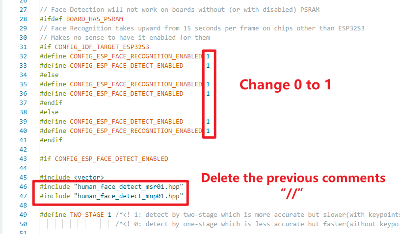
Enable facial recognition:
‼️ The ESP32 version in the Arduino IDE must be ≤3.0.7 to function properly!! Otherwise, you will need to download the required libraries yourself!!
- Open the
app_httpd.cppfile within the example programme and modify the following content:
As this instance will also utilise the camera functionality, it is necessary to verify that PSRAM is enabled prior to flashing.
-
Initialising the ESP32-S3 camera: Configure camera parameters (resolution, pixel format, JPEG quality, etc.), supporting OV3660/OV5640 sensors. Prioritises PSRAM usage for enhanced performance. Failed camera initialisation will print error messages to the serial port.
-
Enabling WiFi configuration hotspot (AP mode): Upon power-up, automatically creates a WiFi hotspot named
ESP32-CAM-SETUPwith password12345678for mobile/computer connection during subsequent configuration. -
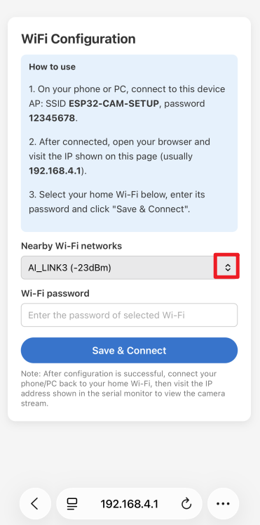
Provides web-based WiFi configuration interface: After connecting to the hotspot, accessing
192.168.4.1:82opens the configuration page, which automatically scans and displays nearby WiFi networks. -
Saves and Connects to Home WiFi (STA Mode): After selecting your home WiFi network, entering its password, and submitting on the configuration page, the device will disconnect its own hotspot and attempt to connect to the selected home WiFi network, waiting for up to 20 seconds.
-
Serial port prints key status information: Includes camera initialisation results, WiFi connection progress, device IP address upon successful connection, and camera service readiness prompts, facilitating debugging and monitoring.
-
Launches camera streaming service: Upon successful WiFi connection, the camera's HTTP service automatically starts. Access the web page using the device IP printed via the serial port to view the camera's live video stream.
-
Automatically terminates configuration service: Upon completing WiFi configuration and successfully connecting to the home network, the WiFi configuration web service (port 82) is automatically deactivated to release associated resources.
-
Supports LED flash configuration (optional): If the camera's pin definitions include a flash pin, the flash functionality is automatically initialised to accommodate supplementary lighting requirements.
-
Adaptive Hardware Resource Allocation: When PSRAM is detected, the system enhances JPEG image quality and increases frame buffer capacity. Without PSRAM, resolution is automatically reduced to prevent memory exhaustion.
-
Dual Pixel Format Purpose: JPEG format is used by default for video streaming transmission. Alternatively, it can be switched to RGB565 format, reserving an interface for subsequent facial detection/recognition functionality.
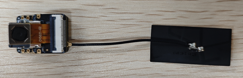
Hardware connection
- Connect the board to the computer using a USB cable
- Insert the SD card and OV5640 camera into the expansion board, then connect the main board to the expansion board
- Connect the antenna to the corresponding port (refer to the hardware connection section in [[#06_wifi_finding]] for specific instructions)
Operational performance
-
Open the serial monitor to view the serial output information. First, connect to the device's Wi-Fi using either a mobile device or computer.
- Network name:
ESP32-CAM-SETUP, Password:12345678
- Network name:
-
Once connected, access
http://192.168.4.1:82based on the serial port information. -
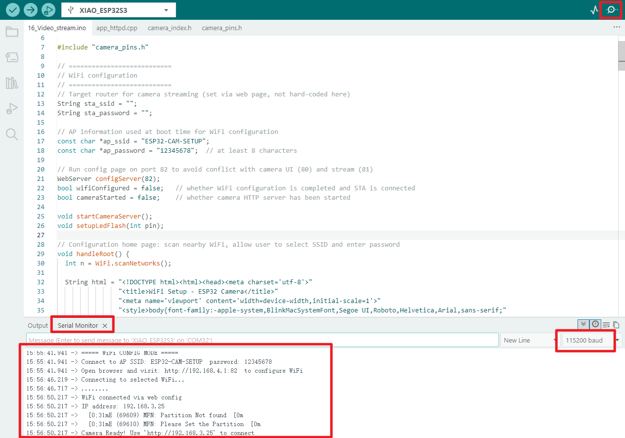
Select the Wi-Fi network you wish to connect to and enter the password. Once connected successfully, the serial monitor will output.
15:56:46.219 -> Connecting to selected WiFi...
15:56:46.717 -> ........
15:56:50.217 -> WiFi connected via web config
15:56:50.217 -> IP address: 192.168.3.25
15:56:50.217 -> [0;31mE (69609) MFN: Partition Not found[0m
15:56:50.217 -> [0;31mE (69610) MFN: Please Set the Partition[0m
15:56:50.217 -> Camera Ready! Use 'http://192.168.3.25' to connect
- Next, following the prompt displayed via the serial port output, use a computer or mobile device on the same network segment to access
http://192.168.3.25
💡 It is recommended to use Microsoft Edge or Google Chrome browsers for access
‼️ Your IP address may differ from mine; pay close attention to the specific details displayed in the device's serial port output when determining the actual access address
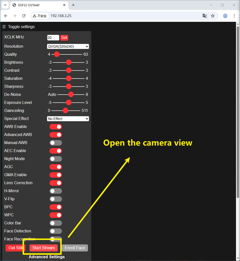
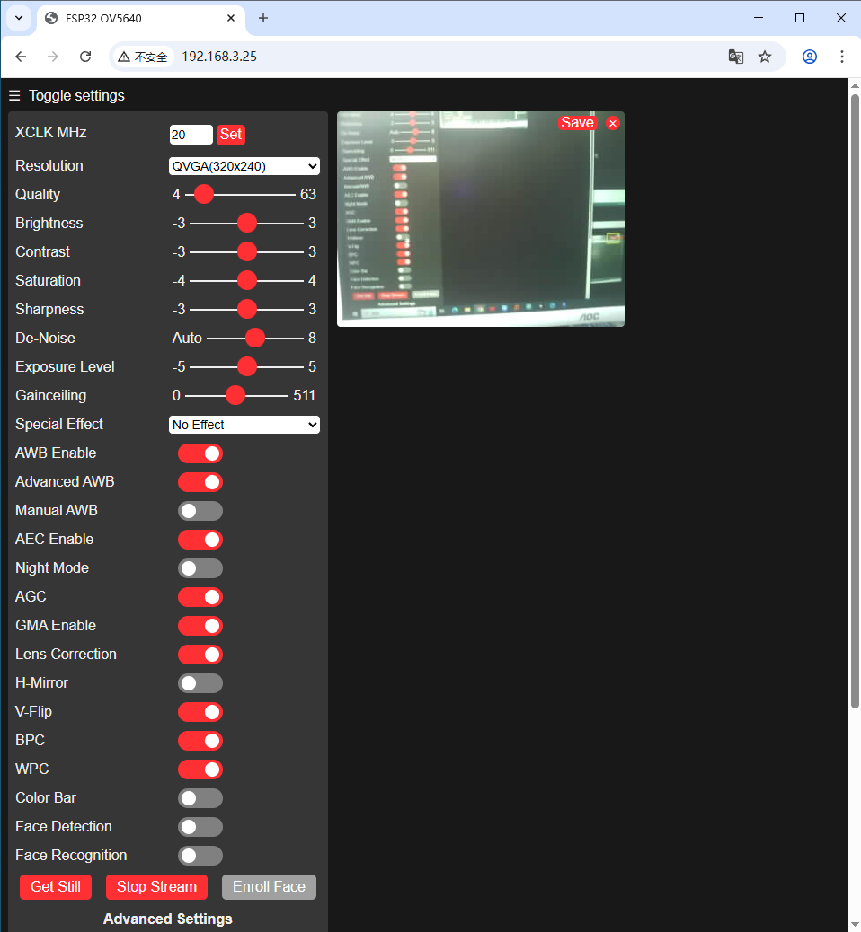
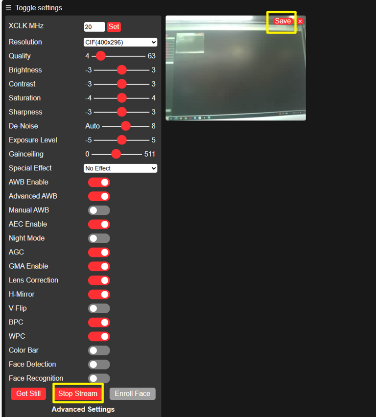
- Visit the website displaying the serial monitor output to view the camera feed online. Upon clicking the
Start Streambutton, the camera feed will be activated.
- Displayed effect
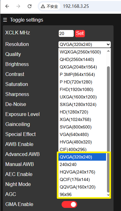
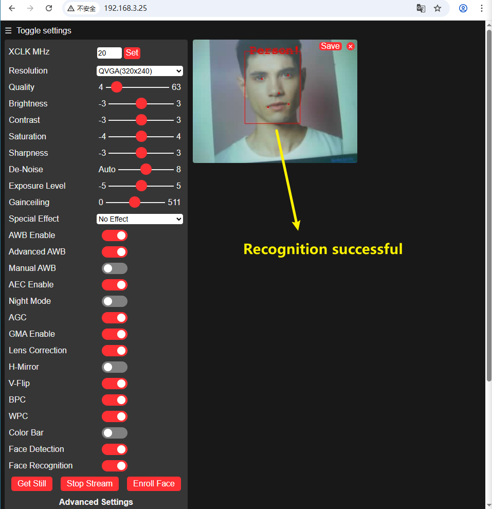
- Enable the
Face DetectionandFace Recognitionoptions to detect human faces.
‼️ Once face recognition is activated, for performance reasons, the image quality must not exceed CIF resolution; otherwise, an error message will appear on the webpage.
 | |
|---|
- Detection successful
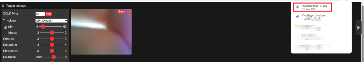
- Clicking the
Savebutton will directly save the current screen locally injpgformat.
17_Video_recording
Programme Description
💡NOTE
It is not recommended to perform video encoding and file export operations directly on the MCU hardware platform. The core reasons are as follows: at present, video encoding library resources compatible with the MCU architecture are relatively scarce. Moreover, the complete video encoding process involves cumbersome operations and complex logic, presenting a high technical barrier for developers.
It should be specifically noted that this example project does not incorporate any standardised video encoding workflow. The final AVI format video file is generated by stitching together MJPG images captured frame by frame. Consequently, videos recorded using this approach may not achieve ideal standards in terms of image quality and smoothness. The core objective of this tutorial is to provide developers with a straightforward technical approach and practical method for implementing periodic recording and storage of short videos.
- Configure camera pins and parameters (JPEG format, SVGA resolution, PSRAM buffer, etc.)
- Initialise camera; if failed, output error code via serial port and terminate; if successful, mark camera as available
- Initialise SD card; detect card type (MMC/SDSC/SDHC); if no card present or initialisation failed, terminate; if successful, mark SD card as available
- Serial port prompts "Recording commences in 1 minute", indicating readiness
- When both camera and SD card are available, initiate video recording every 60 seconds
- Generate AVI filenames sequentially, creating/opening corresponding video files on SD card
- Record 10-second video segments by cyclically acquiring camera frame data and writing to file, then releasing frame buffer
- Upon completion, close the video file; serial port prompts "Saved successfully" with incremented video sequence number
- Delay to fill remaining minute duration, then await next recording cycle
We have previously mastered the techniques for capturing camera images and understand the fundamental nature of moving video—composed of a continuous sequence of static frames.
Based on this principle, this chapter will focus on a practical project: writing a programme to record a 10-second video clip every minute and automatically save the video file to a microSD card, thereby effortlessly accomplishing the periodic capture and local storage of video footage.
As this instance will also utilise the camera functionality, it is necessary to verify that PSRAM is enabled prior to flashing.
Hardware connection
- Connect the board to the computer using a USB cable
- Insert the SD card and OV5640 camera into the expansion board, then connect the expansion board to the mainboard
- Connect the antenna to the corresponding port (refer to the hardware connection section in [[#06_wifi_finding]] for specific instructions)
Operational Effect
- Open the serial monitor to verify whether the programme functions are initiating correctly.
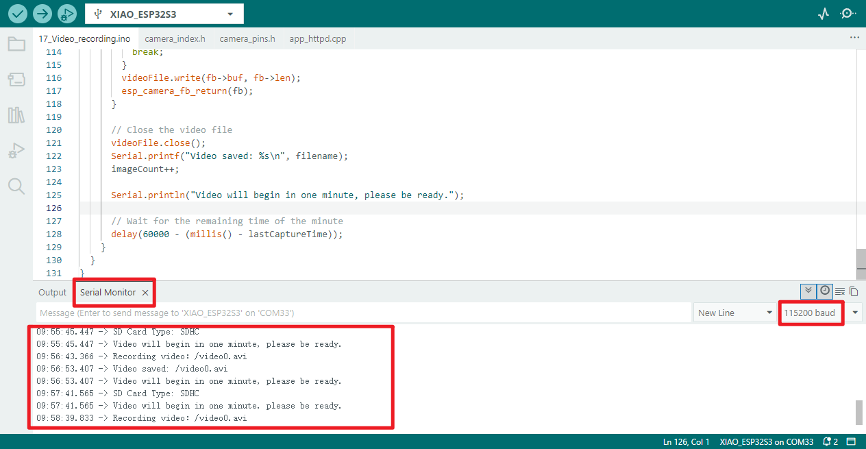
- Following the serial monitor prompts, the video will be saved to the SD card upon completion of recording, named
video0.avi. - Below is a screenshot of viewing the SD card contents via the mobile app, confirming that
video0.avihas been successfully saved and plays correctly.
18_All_example
Programme Description
- Hardware Adaptation: Define hardware pins for components including LEDs, IMU, digital microphones, ADCs, and OV5640 cameras; resolve pin conflicts involving GPIO48 (RGB light / camera multiplexing).
- Full Hardware Inspection: Sequentially test seven functions including IMU, digital microphone, SD card, camera, WiFi, BLE, and ADC; serial port prints each test result (PASS/FAIL).
- Pin management: Release GPIO48 prior to camera testing (disable RGB light output) to prevent interference from pin multiplexing;
- Fault Alarm: When hardware testing fails, the USER LED or RGB light flashes red depending on the camera status to indicate a fault.
- WiFi Testing: Verify WiFi AP mode only (creating the "ESP32-CAM-SETUP" hotspot), serial port prints AP IP and test results;
- Data Output: Upon successful completion of all hardware tests, serial port output shall print IMU (accelerometer / gyroscope / temperature), ADC (raw values / actual voltage), and SD card (capacity / usage) data at one data point per second.
- Resource Management: Release hardware resources such as the camera and I2S after testing, ensuring the SD card's CS pin (shared with the USER LED) maintains a normal logic level.
- Serial Port Debugging: Initialise the serial port at 115200 baud rate, printing test procedures, results, and hardware data to facilitate debugging and troubleshooting.
Hardware connection
All hardware must be connected to verify that each component functions correctly.
Motherboard:
 |  |
|---|---|
| All accessories: | |
 |
Complete connection diagram:
|  |
|
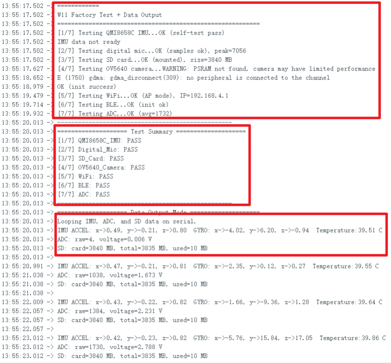
Operational performance
Serial monitor output: There are three distinct output sections:
- Sequential testing of each device
- Results following testing of all devices
- Continuous output of IMU, ADC, and SD card data once all devices pass testing
19_Expansion_Display
Programme Description
- Display driver: Controls a 1.54-inch ST7789 display (240×240 resolution), illuminates the backlight, and fills the entire screen with a white background colour.
- Logo Display: Display a preset logo image at the centre of the screen;
- RGB light control: Drives the WS2812 RGB light via GPIO48 pin, with default brightness set to 64. Initially displays red, cycling through red/green/blue every 2 seconds.
- Sensor Acquisition: Drives the QMI8658C six-axis motion sensor, updating acceleration (X/Y/Z), gyroscope (X/Y/Z) data, and sensor temperature every 500 milliseconds.
- Data display: Real-time presentation on the screen of sensor acceleration, gyroscope, and temperature data, alongside the current colour status of the RGB lights;
- Interface refresh: The display status interface refreshes every second by default, with immediate updates when RGB lighting colours change to ensure real-time information.
- Sensor Configuration: Set parameters for the QMI8658C sensor (accelerometer range 4G, gyroscope range 64DPS, etc.) to ensure data acquisition accuracy.
🔍:
logo_rgb565: An array defined inlogo_rgb565.h, storing the RGB565 values for each pixel of the logo;draw16bitRGBBitmap: A function specifically designed for rendering RGB565 format images, better suited to the ST7789 display than the standard drawBitmap function.
Hardware connection
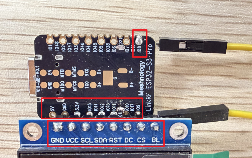
Require self-soldering of pins. Screen interface corresponds to device interface:
| W11 | 1.54inch | |
|---|---|---|
| pin | GND | GND |
| pin | 3.3V | VCC |
| pin | GPIO13 | SCL |
| pin | GPIO12 | SDA |
| pin | GPIO11 | RST |
| pin | GPIO10 | DC |
| pin | GPIO9 | CS |
| pin | GPIO8 | BL |
| Simplified connection diagram: |
Overall connection diagram:
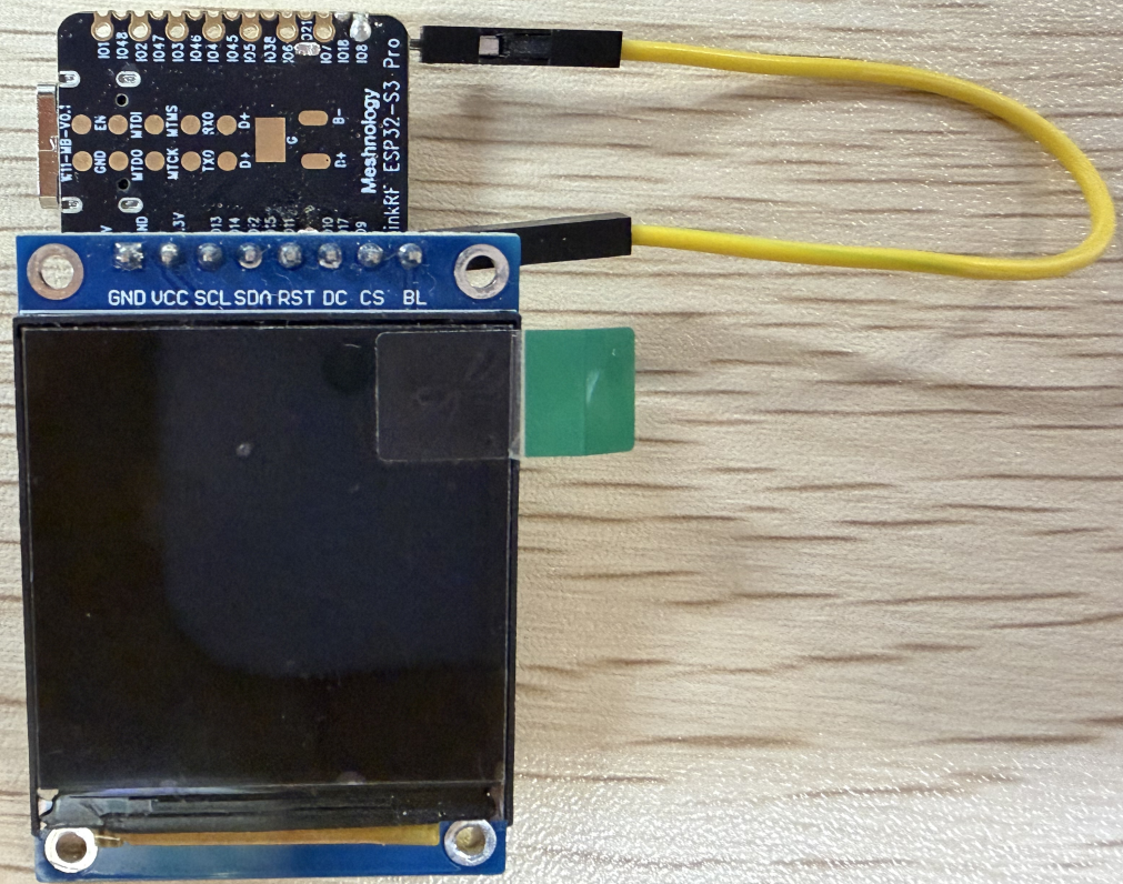
Operational performance
Directly above is the logo
Next is the IMU data information: AX, AY, AZ correspond respectively to: ACCEL's X, Y, Z GX, GY, GZ correspond respectively to: the X, Y, and Z axes of the gyroscope.
Then comes the display of the RGB LED lights.
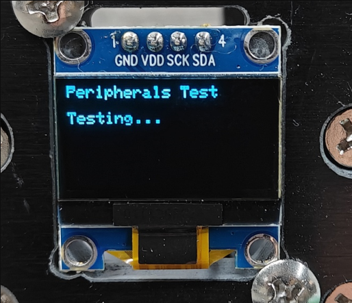
20_ALL_OLED(0.96inch)
Programme Description
- OLED Driver: Controls the SSD1306 display (128×64), I2C address 0x3C, using a dedicated bus to avoid conflicts;
- Peripheral Self-Test: Automatically tests seven major hardware components (IMU, microphone, SD card, camera, Wi-Fi, BLE, ADC), outputting PASS/FAIL;
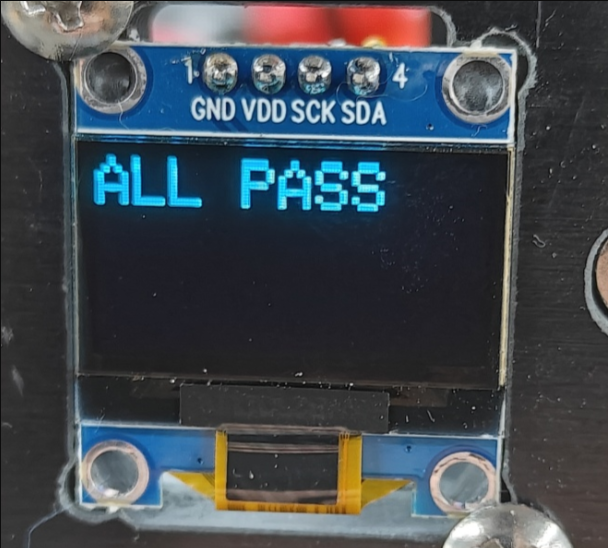
- Result Display: The OLED displays the test status; if all components are functioning normally, it displays ‘ALL PASS’; if there is an anomaly, it displays the name of the failed peripheral;
- Sensor Data Acquisition: Drives the QMI8658C six-axis sensor, outputting acceleration, gyroscope and temperature data;
- Data Display: The OLED displays IMU data, SD card capacity and ADC voltage in real time, whilst detailed data is output via the serial port in real time;
- Interface Refresh: The OLED refreshes every 500 ms, and the serial port outputs data every 1 second;
- Resource Management: Automatically releases RGB pins for the camera and caches SD card information to prevent system lag.
🔍 Key Notes:
WireOLED: A dedicated I2C bus for OLED displays, designed to prevent conflicts with the IMU;Adafruit_SSD1306: An OLED driver library responsible for clearing the screen, drawing text and refreshing the display.
Hardware connections
VCC --> 3.3V GND --> GND SCL --> GPIO8 SDA --> GPIO7
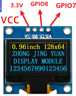
Performance
The results of all peripheral device scans will be displayed on the screen
If all peripheral checks are successful, the screen will display the message ‘ALL PASS’.
Resource downloads
Arduino deme:
As the file is too large, it has been split into separate downloads, but it will still work perfectly fine!
Flashing tool:
Hardware specifications:
W11-Expansion board_Schematic diagram