N40 ESP32 Extension Board
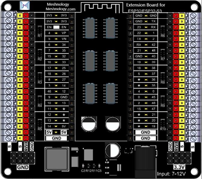
The N40 is an expansion and breakout board for compatible ESP32 and ESP32-S3 development boards. It brings the GPIO, power, enable, and communication pins to clearly labeled 2.54 mm headers and screw terminals, making it easier to connect external modules, prototype circuits, and measure signals.
Key Features
- Breaks out the ESP32/ESP32-S3 GPIO and power pins for convenient access
- 2.54 mm pin headers for Dupont-wire connections
- 2.54 mm-pitch KF screw terminals for direct wire connections
- Dedicated 5 V and GND distribution headers
- GPIO status LEDs for visual signal indication
- TXS0108EPWR level-translation ICs with a specified data rate of up to 60 Mbps
- 7-12 V DC input through a 5.5 x 2.1 mm barrel connector
- Four 3 mm mounting holes
Compatible Core Boards
The extension board is designed for compatible ESP32 and ESP32-S3 boards with the required header arrangement. The product specification lists the following core-board options:
- ESP32-WROOM development board
- ESP32-S3-WROOM development board
- YD-ESP32-S3 N16R8 development board
ESP32 development boards are available with different dimensions and pin arrangements. Before applying power, verify that the core board matches the N40 socket spacing and that every 3.3 V, 5 V, GND, RST, TX, and RX pin is correctly aligned.
Specifications
| Item | Specification |
|---|---|
| Product | N40 ESP32 Extension Board V1 |
| DC input connector | 5.5 x 2.1 mm barrel connector |
| Input power | 7-12 V DC, 2 A |
| Recommended adapter | 12 V DC, 2 A |
| Core-board female headers | 44 pins, 25.4 mm row spacing |
| GPIO pin-header pitch | 2.54 mm |
| Power-header pitch | 2.54 mm |
| KF terminal pitch | 2.54 mm |
| GPIO indicator color | Yellow-green |
| Level translation | TXS0108EPWR, up to 60 Mbps |
| Mounting holes | 3 mm diameter |
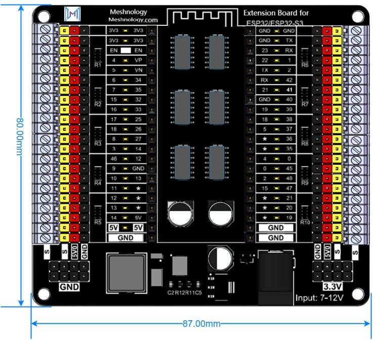
| Mounting-hole spacing | 80.20 x 73.20 mm |
| Board dimensions | 87.00 x 80.00 x 12.00 mm |
| Operating temperature | -20 to 70 °C |
Board Overview
The N40 provides three connection methods around the core-board sockets:
- Signal headers - Use 2.54 mm Dupont leads to access GPIO, communication, reset, and power pins.
- Power distribution headers - Use the dedicated 5 V and GND rows to power external sensors and modules.
- KF screw terminals - Insert stripped wires and tighten the terminal screws for a secure connection.
The GPIO LEDs are connected to the corresponding core-board signals and provide a visual indication when the logic state changes.
Power Supply
Connect a regulated 7-12 V DC supply to the 5.5 x 2.1 mm barrel connector. A 12 V/2 A adapter is recommended.
Confirm the adapter voltage, polarity, and core-board orientation before switching on the power. Do not connect an external supply directly to a GPIO pin.
Header Functions
| Header | Function |
|---|---|
| J1, J3, J9 | Break out the left-side GPIO, power, and enable pins of the installed core board |
| J2, J4, J10 | Break out the right-side GPIO, power, and communication pins of the installed core board |
| J5, J6 | Ground distribution; pins 1-22 are GND |
| J7, J8 | 5 V distribution; pins 1-22 provide 5 V for external devices |
| J0 | 7-12 V DC power input |
J1, J3, and J9 Pin Definition
| Pin | Name | Type | Function |
|---|---|---|---|
| 1 | 3.3V | P | 3.3 V output for an external sensor |
| 2 | 3.3V | P | 3.3 V output for an external sensor |
| 3 | RST | I | CHIP_PU; connected to the reset switch |
| 4 | GPIO4 | I/O | GPIO4, TOUCH4, ADC1_CH3 |
| 5 | GPIO5 | I/O | GPIO5, TOUCH5, ADC1_CH4 |
| 6 | GPIO6 | I/O | GPIO6, TOUCH6, ADC1_CH5 |
| 7 | GPIO7 | I/O | GPIO7, TOUCH7, ADC1_CH6 |
| 8 | GPIO15 | I/O | GPIO15, U0RTS, ADC2_CH4, XTAL_32K_P |
| 9 | GPIO16 | I/O | GPIO16, U0CTS, ADC2_CH5, XTAL_32K_N |
| 10 | GPIO17 | I/O | GPIO17, U1TXD, ADC2_CH6 |
| 11 | GPIO18 | I/O | GPIO18, U1RXD, ADC2_CH7, CLK_OUT3 |
| 12 | GPIO8 | I/O | GPIO8, TOUCH8, ADC1_CH7, SUBSPICS1 |
| 13 | GPIO3 | I/O | GPIO3, TOUCH3, ADC1_CH2 |
| 14 | GPIO46 | I/O | GPIO46 |
| 15 | GPIO9 | I/O | GPIO9, TOUCH9, ADC1_CH8, SUBSPIHD, FSPIHD |
| 16 | GPIO10 | I/O | GPIO10, TOUCH10, ADC1_CH9, FSPIIO4, SUBSPICS0, FSPICS0 |
| 17 | GPIO11 | I/O | GPIO11, TOUCH11, ADC2_CH0, FSPIIO5, SUBSPID, FSPID |
| 18 | GPIO12 | I/O | GPIO12, TOUCH12, ADC2_CH1, FSPIIO6, SUBSPICLK, FSPICLK |
| 19 | GPIO13 | I/O | GPIO13, TOUCH13, ADC2_CH2, FSPIIO7, SUBSPIQ, FSPIQ |
| 20 | GPIO14 | I/O | GPIO14, TOUCH14, ADC2_CH3, FSPIDQS, SUBSPIWP, FSPIWP |
| 21 | 5V | P | 5 V power supply |
| 22 | GND | P | Ground |
J2, J4, and J10 Pin Definition
| Pin | Name | Type | Function |
|---|---|---|---|
| 1 | GND | P | Ground |
| 2 | TX | I/O | GPIO43, U0TXD, CLK_OUT1 |
| 3 | RX | I/O | GPIO44, U0RXD, CLK_OUT2 |
| 4 | GPIO1 | I/O | GPIO1, TOUCH1, ADC1_CH0 |
| 5 | GPIO2 | I/O | GPIO2, TOUCH2, ADC1_CH1 |
| 6 | GPIO42 | I/O | GPIO42, MTMS |
| 7 | GPIO41 | I/O | GPIO41, CLK_OUT1, MTDI |
| 8 | GPIO40 | I/O | GPIO40, CLK_OUT2, MTDO |
| 9 | GPIO39 | I/O | GPIO39, CLK_OUT3, SUBSPICS1, MTCK |
| 10 | GPIO38 | I/O | GPIO38, FSPIWP, SUBSPIWP |
| 11 | GPIO37 | I/O | GPIO37, FSPIQ, SUBSPIQ, SPIDQS |
| 12 | GPIO36 | I/O | GPIO36, FSPICLK, SUBSPICLK, SPIIO7 |
| 13 | GPIO35 | I/O | GPIO35, FSPID, SUBSPID, SPIIO6 |
| 14 | GPIO0 | I/O | GPIO0 |
| 15 | GPIO45 | I/O | GPIO45 |
| 16 | GPIO48 | I/O | GPIO48, SPICLK_N |
| 17 | GPIO47 | I/O | GPIO47, SPICLK_P |
| 18 | GPIO21 | I/O | GPIO21 |
| 19 | GPIO20 | I/O | GPIO20, U1CTS, ADC2_CH9, CLK_OUT1, USB_D+ |
| 20 | GPIO19 | I/O | GPIO19, U1RTS, ADC2_CH8, CLK_OUT2, USB_D- |
| 21 | GND | P | Ground |
| 22 | GND | P | Ground |
Type legend: P = power, I = input, I/O = input/output.
Dimensions
The extension board measures 87.00 x 80.00 x 12.00 mm. The mounting-hole center spacing is 80.20 x 73.20 mm, and the mounting holes accept 3 mm screws.
Package Contents
| Item | Quantity | Notes |
|---|---|---|
| N40 ESP32 Extension Board V1 | 1 | Included |
| 12 V/2 A power adapter | 1 | Included according to the supplied product specification |
| ESP32-WROOM core board | 1 | Optional |
| ESP32-S3-WROOM core board | 1 | Optional |
| YD-ESP32-S3 N16R8 core board | 1 | Optional |
Package contents may vary by product option. Check the selected product configuration before ordering.